
PN-UN553S - Uncategorized SHARP - Free user manual and instructions
Find the device manual for free PN-UN553S SHARP in PDF.


| Product Type | Professional LCD Display |
| Brand | Sharp |
| Model | PN-UN553S |
| Screen Size | 55 inches (diagonal) |
| Native Resolution | 3840 x 2160 (4K UHD) |
| Panel Type | LCD with Direct LED backlight |
| Brightness | 700 cd/m² |
| Contrast Ratio | 4000:1 (typical) |
| Response Time | 8 ms (Gray-to-Gray) |
| Viewing Angles | 178° horizontal / 178° vertical |
| Supported Orientation | Landscape and Portrait |
| Video Inputs | HDMI, DisplayPort, DVI-D, VGA |
| Control Interfaces | RS-232C, LAN (web control) |
| Power Consumption (Max) | 240 W |
| Standby Power | < 0.5 W |
| Power Supply | AC 100-240V, 50/60 Hz |
| VESA Mounting | 400 x 400 mm |
| Dimensions (W x H x D) | 1245.7 x 717.8 x 56.2 mm (without stand) |
| Weight | 24.5 kg |
| Operating Temperature | 0°C to 40°C |
| Operating Humidity | 20% to 80% RH (non-condensing) |
| Intended Usage | Digital signage, commercial displays, 24/7 operation |
| Warranty | 3 years (typical) |
Frequently Asked Questions - PN-UN553S SHARP
User questions about PN-UN553S SHARP
0 question about this device. Answer the ones you know or ask your own.
Ask a new question about this device
Download the instructions for your Uncategorized in PDF format for free! Find your manual PN-UN553S - SHARP and take your electronic device back in hand. On this page are published all the documents necessary for the use of your device. PN-UN553S by SHARP.
USER MANUAL PN-UN553S SHARP
Safety Precautions, Maintenance &
Recommended Use....3
Safety Precautions and Maintenance....3
Recommended Use....3
Cleaning the LCD Panel....4
Cleaning the Cabinet....4
Chapter 1 Installation
Setup Overview 6
Mounting....8
Mounting location 10
Orientation....10
Ventilation Requirements....11
Attaching Mounting Accessories.... 12
Using a Wall Mount Adapter....12
Installing an Option Board 13
Installing an Optional Sensor Unit 14
Chapter 2 Parts Name and Functions
Control Panel....16
Terminal Panel....17
Wireless Remote Control (Optional)....19
Chapter 3 Connections
Wiring Diagram....22
Connections.... 22
External Video Connections 23
Connecting to a Personal Computer 23
Connecting to a Media Device with HDMI....24
Internal Video Sources 25
Media Player.... 26
Option Boards for the Monitor 27
Connecting a USB Device....28
Chapter 4 Basic Operation
Power ON and OFF....30
Operating Range for the Optional Remote Control .. 31
Using Power Management 31
Menu item details 31
Showing the Information OSD....32
Switching Between Picture Modes 32
Setting the Aspect Ratio....33
Using Point Zoom....34
OSD (On-Screen-Display) Controls.... 35
Using the Media Player 37
File Display Screen.... 38
Playing Files 39
Configuring the Slideshow Settings....40
Enabling Auto Play 41
Displayable/Playable Files.... 42
Chapter 5 Advanced Operation
Creating a Power Schedule....44
Advanced Color Adjustment 45
Using the SpectraView Engine....45
Using Stand-alone calibration.... 48
Using Other Picture Modes 51
Multi-Picture Mode.... 52
PIP (Picture-In-Picture) matrix....54
Setting Security and Locking the Monitor Controls... 56
Password Security....56
Locking the Button Controls .... 57
Media Player Settings.... 60
Network & Other Settings....61
Copying Files to the microSD memory card....62
Chapter 6 Multi-Monitor Setup
Connecting Multiple Monitors 68
Video Out Connection 70
Setting the Remote Control ID Function....71
Chapter 7 External Control
Connecting Interfaces.... 74
Commands 74
Supporting HDMI CEC Command....76
Controlling the Monitor via RS-232C....77
Controlling the Monitor via LAN....78
Multiple Monitors Connection 79
Network Setting by Using an HTTP Browser......80
OSD Menu Settings in the Monitor Web controls.....81
Network Settings 82
Proof of Play....86
Chapter 8 Troubleshooting
Screen Image and Video Signal Issues......88
Hardware Issues.... 89
Image Persistence....91
Chapter 9 Specifications
PN-UN553S....93
PN-UN553V....94
Appendix A External Resources
Appendix B OSD Controls List
INPUT....98
MULTI-DISPLAY....109
PICTURE....98
DISPLAY PROTECTION....112
AUDIO 103
CONTROL....113
SCHEDULE....103
OPTION....118
MULTI-INPUT 105
SYSTEM....118
OSD....108

Information on the Disposal of this Equipment
IF YOU WISH TO DISPOSE OF THIS EQUIPMENT, DO NOT USE THE ORDINARY WASTE BIN, AND DO NOT PUT THEM INTO A FIREPLACE!
Used electrical and electronic equipment should always be collected and treated SEPARATELY in accordance with local law. Separate collection promotes an environment-friendly treatment, recycling of materials, and minimizing final disposal of waste. IMPROPER DISPOSAL can be harmful to human health and the environment due to certain substances! Take USED EQUIPMENT to a local, usually municipal, collection facility, where available.
If in doubt about disposal, contact your local authorities or dealer and ask for the correct method of disposal.
ONLY FOR USERS IN THE EUROPEAN UNION, AND SOME OTHER COUNTRIES; FOR INSTANCE NORWAY AND SWITZERLAND: Your participation in separate collection is requested by law.
The symbol shown above appears on electrical and electronic equipment (or the packaging) to remind the users of this.
Users from PRIVATE HOUSEHOLDS are requested to use existing return facilities for used equipment. Return is free of charge.
If the equipment has been used for BUSINESS PURPOSES, please contact your SHARP dealer who will inform you about take-back. You might be charged for the costs arising from take-back. Small equipment (and small quantities) might be taken back by your local collection facility. For Spain: Please contact the established collection system or your local authority for take-back of your used products.
Registration Information
Cable Information
CAUTION: Use the provided specified cables with this product so as not to interfere with radio and television reception.
For DVI, USB and mini D-Sub 15-pin, please use a shielded signal cable.
For HDMI, DisplayPort and D-Sub 9-pin, please use a shielded signal cable.
Use of other cables and adapters may cause interference with radio and television reception.
WARNING:
FCC Regulations state that any unauthorized changes or modifications to this equipment not expressly approved by the manufacturer could void the user's authority to operate this equipment.
NOTE:
This equipment has been tested and found to comply with the limits for a Class B digital device, pursuant to Part 15 of the FCC Rules. These limits are designed to provide reasonable protection against harmful interference in a residential installation.
This equipment generates, uses and can radiate radio frequency energy and, if not installed and used in accordance with the instructions, may cause harmful interference to radio communications. However, there is no guarantee that interference will not occur in a particular installation.
If this equipment does cause harmful interference to radio or television reception, which can be determined by turning the equipment off and on, the user is encouraged to try to correct the interference by one or more of the following measures:
- Reorient or relocate the receiving antenna.
- Increase the separation between the equipment and receiver.
- Connect the equipment into an outlet on a circuit different from that to which the receiver is connected.
- Consult the dealer or an experienced radio/TV technician for help.
U.S.A. ONLY
Supplier's Declaration of Conformity
SHARP LCD MONITOR, PN-UN553S, PN-UN553V
This device complies with Part 15 of the FCC Rules. Operation is subject to the following two conditions: (1)
This device may not cause harmful interference, and (2) this device must accept any interference received, including interference that may cause undesired operation.
Responsible Party:
SHARP ELECTRONICS CORPORATION
100 Paragon Drive, Montvale, NJ 07645
TEL: 1-888-GO-SHARP / 1-888-467-4277 www.sharpusa.com
U.S.A. ONLY
Microsoft and Windows are trademarks of the Microsoft group of companies.
DisplayPort and DisplayPort Compliance Logo are trademarks owned by Video Electronics Standards Association in the United States and other countries.
All other brands and product names are trademarks or registered trademarks of their respective owners.
The terms HDMI, HDMI High-Definition Multimedia Interface, HDMI Trade dress and the HDMI Logos are trademarks or registered trademarks of HDMI Licensing Administrator, Inc.
Trademark PJLink is a trademark applied for trademark rights in Japan, the United States of America and other countries and areas.
microSD and microSD SDHC logos are trademarks of SD-3C, LLC.
Adobe, Acrobat, and Acrobat Reader are either registered trademarks or trademarks of Adobe in the United States and/or other countries.
GPL/LGPL Software Licenses
The product includes software licensed under GNU General Public License (GPL), GNU Lesser General Public License (LGPL), and others.
For more information on each software, please visit the global website.
https://jp.sharp/business/lcd-display/support/download/source_e.html
Important Information

WARNING

TO PREVENT FIRE OR SHOCK HAZARDS, DO NOT EXPOSE THIS UNIT TO RAIN OR MOISTURE. ALSO, DO NOT USE THIS UNIT'S POLARIZED PLUG WITH AN EXTENSION CORD RECEPTACLE OR OTHER OUTLETS UNLESS THE PRONGS CAN BE FULLY INSERTED.
REFRAIN FROM OPENING THE CABINET AS THERE ARE HIGH VOLTAGE COMPONENTS INSIDE. REFER SERVICING TO QUALIFIED SERVICE PERSONNEL.

CAUTION

TO REDUCE THE RISK OF ELECTRIC SHOCK, MAKE SURE POWER CORD IS UNPLUGGED FROM WALL SOCKET. TO FULLY DISENGAGE THE POWER TO THE UNIT, PLEASE DISCONNECT THE POWER CORD FROM THE AC OUTLET. DO NOT REMOVE COVER (OR BACK). NO USER SERVICEABLE PARTS INSIDE. REFER SERVICING TO QUALIFIED SERVICE PERSONNEL.

This symbol warns user that uninsulated voltage within the unit may have sufficient magnitude to cause electric shock. Therefore, it is dangerous to make any kind of contact with any part inside this unit.

This symbol alerts the user that important literature concerning the operation and maintenance of this unit has been included. Therefore, it should be read carefully in order to avoid any problems.
This equipment is designed to be used in the condition of the power cord connected to earth. If the power cord is not connected to the earth, it may cause electric shock. Please make sure the power cord is earthed properly.
* When operating the monitor with its AC 125-240 V power supply, use a power supply cord that matches the power supply voltage of the AC power outlet being used.
NOTE: This product can only be serviced in the country where it was purchased.
Use the power cord which has BSMI mark at both ends when you use this monitor in Taiwan.
• The intended primary use of this product is as an Information Technical Equipment in an office or domestic environment.
- The product is intended to be connected to a computer and is not intended for the display of television broadcast signals.
NOTE: (1) The contents of this user's manual may not be reprinted in part or whole without permission.
(2) The contents of this user's manual are subject to change without notice.
(3) Great care has been taken in the preparation of this user's manual; however, should you notice any questionable points, errors or omissions, please contact us.
(4) Notwithstanding article (3), SHARP will not be responsible for any claims on loss of profit or other matters deemed to result from using this device.
- The TFT color LCD panel used in this monitor is made with the application of high precision technology. However, there may be minute points on the screen where pixels never light or are permanently lit. Also, if the screen is viewed from an acute angle there may be uneven colors or brightness. Please note that these are not malfunctions but common phenomena of LCDs and will not affect the performance of the monitor.
- Do not display a still picture for a long period, as this could cause a residual image.
Safety Precautions, Maintenance & Recommended Use
Safety Precautions and Maintenance
FOR OPTIMUM PERFORMANCE, PLEASE NOTE THE FOLLOWING WHEN SETTING UP AND USING THE MULTI-FUNCTION MONITOR:
- DO NOT OPEN THE MONITOR. There are no user serviceable parts inside and opening or removing covers may expose you to dangerous shock hazards or other risks. Refer all servicing to qualified service personnel.
- Use only the power cord supplied with the monitor.
- Do not bend, crimp or otherwise damage the power cord.
- Do not place any heavy objects on the power cord. Damage to the cord may cause shock or fire.
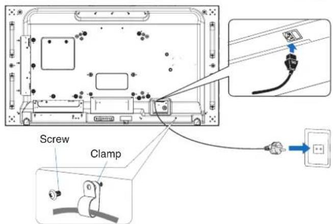
- Fasten the power cord to the monitor by attaching the screw and clamp to prevent loose connection. (Recommended Fasten Force: 139 - 189 N·cm).
- Please make sure that enough power is supplied to the monitor. Please refer to the "Power Supply" in the specifications.
- The power supply cord you use must have been approved by and comply with the safety standards of your country. (e.g. Type H05VV-F 3G 1 mm² should be used in Europe).
- In the UK use a BS-approved power cord with a molded plug having a black (5 A) fuse installed for use with this monitor.
- The power cord connector is the primary means of detaching the system from the power supply. The monitor should be installed close to a power outlet that is easily accessible.
- Do not spill any liquids into the cabinet or use your monitor near water.
- Do not insert objects of any kind into the cabinet slots, as they may touch dangerous voltage points, which can be harmful or fatal, or may cause electric shock, fire or equipment failure.
- Do not place this product on a sloping or unstable cart, stand or table, as the monitor may fall, causing serious damage to the monitor.
- Do not mount this product face up, face down, or upside down for an extended period of time as it may cause permanent damage to the screen.
- Do not use the monitor outdoors.
- If glass is broken, handle with care.
- This monitor is equipped with temperature control fans. For reliable performance and long life use of this product, it is required that the vents on the monitor are not covered.
- If the monitor or glass is broken, do not come in contact with the liquid crystal and handle with care.
- Allow adequate ventilation around the monitor, so that heat can properly dissipate.
- Do not block ventilated openings or place the monitor near a radiator or other heat source.
-
Do not put anything on top of the monitor.
-
Handle with care when transporting. Save packaging for transporting.
- When running the cooling fan continuously, we recommend wiping clean the ventilation holes a minimum of once a month.
- To ensure the monitor's reliability, please clean the ventilation holes at the rear side of the cabinet at least once a year to remove dirt and dust.
- When using a LAN cable, do not connect to a peripheral device with wiring that might have excessive voltage.
- Do not use the monitor in high temperature, humid, dusty, or oily areas.
- Do not use the monitor under rapid changes in temperature and humidity, and avoid cold air directly from an air-conditioning vent. These conditions may shorten the life of the monitor or cause condensation. If water condensation has occurred, unplug the monitor and do not use the monitor until the condensation has evaporated.
Connecting to a TV *1
- Cable distribution system should be grounded (earthed) in accordance with ANSI/NFPA 70, the National Electrical Code (NEC), in particular Section 820.93, Grounding of Outer Conductive Shield of a Coaxial Cable.
- The screen of the coaxial cable is intended to be connected to earth in the building installation.
Under the following conditions immediately disconnect your monitor from the wall outlet and refer servicing to qualified service personnel:
- If the power supply cord or plug is damaged.
- If liquid has spilled or objects have fallen into the monitor.
- If the monitor has been exposed to rain or water.
- If the monitor has been dropped or the cabinet has been damaged.
- If you notice any structural damage such as cracks or unnatural wobbling.
- If the monitor does not operate normally by following operating instructions.
*1: The product you purchased may not have this feature.
Recommended Use
Ergonomics
To realize the maximum ergonomic benefits, we recommend the following:
- For optimum performance of the monitor, allow 20 minutes for warming up. Avoid reproduction of still patterns on the monitor for long periods of time to avoid image persistence (after image effects).
- Rest your eyes periodically by focusing on an object at least 5 feet away. Blink often.
-
Position the monitor at a 90° angle to windows and other light sources to minimize glare and reflections.
-
Adjust the monitor's brightness, contrast and sharpness controls to enhance readability.
- Get regular eye checkups.
- Use the preset Size and Position controls with standard input signals.
- Use the preset color settings.
- Use non-interlaced signals.
- Do not view the primary color blue on a dark background. It is difficult to see and may cause eye fatigue due to insufficient contrast.
- Suitable for entertainment purposes at controlled luminous environments to avoid disturbing reflections from the screen.
Cleaning the LCD Panel
- When the LCD panel is dusty, please gently wipe with a soft cloth.
- Clean the LCD panel surface with a lint-free, non-abrasive cloth. Avoid using any cleaning solution or glass cleaner!
- Please do not rub the LCD panel with a hard or abrasive material.
- Please do not apply pressure to the LCD panel surface.
- Please do not use OA cleaner as it will cause deterioration or discoloration on the LCD panel surface.
Cleaning the Cabinet
- Unplug the power supply.
- Gently wipe the cabinet with a soft cloth.
- To clean the cabinet, dampen the cloth with a neutral detergent and water, wipe the cabinet and follow with a dry cloth.
NOTE: DO NOT clean with benzene thinner, alkaline detergent, alcoholic system detergent, glass cleaner, wax, polish cleaner, soap powder, or insecticide. Rubber or vinyl should not be in contact with the cabinet for an extended period of time. These types of fluids and materials can cause the paint to deteriorate, crack or peel.
Chapter 1 Installation
This Chapter Includes:
→ "Setup Overview" on page 6
→ "Mounting" on page 8
→ “Attaching Mounting Accessories” on page 12
→ "Installing an Option Board" on page 13
→ "Installing an Optional Sensor Unit" on page 14
CAUTION:
For box contents, please refer to the printed contents sheet provided in the box.
This device cannot be used or installed without the Tabletop Stand or other mounting accessory for support. For proper installation it is strongly recommended to use a trained, SHARP authorized service person. Failure to follow SHARP standard mounting procedures could result in damage to the equipment or injury to the user or installer. Product warranty does not cover damage caused by improper installation. Failure to follow these recommendations could result in voiding the warranty.
Contents
If any component should be missing, please contact your dealer.
| ☐LCD Monitor: 1 | ☐microSD card slot cover: 1 |
| ☐Power cord | ☐Clamp: 1 |
| ☐HDMI cable: 1 | ☐Screw with washer (M4 x 10): 2 |
| ☐LAN cable: 1 | ☐Wall Mount adapter: 4 |
| ☐Displayport cable: 1 | ☐Wall Mount adapter screw (M6 x 35): 4 |
| ☐Setup Manual: 1 |
Please note: do not dispose of batteries in household waste for environmental protection. Follow the disposal instructions for your area.
1. Determine the installation location
CAUTION:
- Before installing this monitor, turn it on and check the display.
- Installing your monitor must be done by a qualified technician. Contact your supplier for more information.
- MOVING OR INSTALLING THE MONITOR MUST BE DONE BY TWO OR MORE PEOPLE. Failure to follow this caution may result in injury if the monitor falls.
- This monitor has internal temperature sensors and cooling fans, including a fan for the Option Board. If the monitor becomes too hot, the cooling fans will turn on automatically.
The Option Board's fan is active although the temperature is lower than normal operating temperature for cooling the Option Board. If the monitor overheats while the cooling fan is running, a “Caution” warning appears. If the “Caution” warning appears, stop using the unit, turn off the power and allow it to cool. Using the cooling fans will reduce the likelihood of early unit failure and may help reduce image degradation and “Image Persistence”.
If the monitor is used in an enclosed area or if the LCD panel is covered with a protective screen, please check the inside temperature of the monitor by using the HEAT STATUS control in the OSD (see page 112). If the temperature is higher than the normal operating temperature, please turn the cooling fan to [ON] within the [FAN CONTROL] menu within the OSD (see page 112).
NOTE: To avoid scratching the LCD panel, always place a soft cloth, such as a blanket that is larger than the monitor's screen area, on the table before laying the monitor face down.
2. Install the remote control (Optional) batteries
1

2

3

- Press the cover gently and slide it in the direction of the arrow.
- See the instructions in the compartment and put in the batteries (R03 or LR03 ("AAA" size) x 2) with their plus (+) and minus (-) sides oriented correctly.
- Close the cover.
SHARP recommends the following battery use:
⚠️ CAUTION: Incorrect usage of batteries can result in leaks or bursting.
- Place "AAA" size batteries matching the (+) and (-) signs on each battery to the (+) and (-) signs of the battery compartment.
- Do not mix battery brands.
- Do not combine new and old batteries. This can shorten battery life or cause liquid leakage of batteries.
- Remove dead batteries immediately to prevent battery acid from leaking into the battery compartment.
- Do not touch exposed battery acid, it may injure your skin.
NOTE: If you do not intend to use the Remote Control for a long period of time, remove the batteries.
3. Connect external equipment (See page 21)
- To protect the external equipment, turn off the main power before making connections.
• Refer to the manual of your equipment for further information.
NOTE: Do not connect/disconnect cables when turning on the monitor or other external equipment as this may result in loss of image.
4. Connect the supplied power cord
- The monitor should be installed close to an easily accessible power outlet.
CAUTION:
- Fasten the power cord to the monitor by attaching the screw and clamp. (Recommended Fasten Force: 139 - 189 N·cm).
- Please make sure that enough power is supplied to the monitor. Please refer to the "Power Supply" in the specification (See "PN-UN553S" on page 93 and "PN-UN553V" on page 94).
WARNING:
- Please refer to the "Important Information" section of this manual for proper selection of an AC power cord.
- Fully insert the prongs into the power outlet socket. A loose connection may cause image instability and may pose a fire hazard.
5. Cable information
CAUTION:
Use the provided specified cables with this product so as not to interfere with radio and television reception.
For DVI, USB and mini D-Sub 15-pin, please use a shielded signal cable.
For HDMI, DisplayPort and D-Sub 9-pin, please use a shielded signal cable.
Use of other cables and adapters may cause interference with radio and television reception.
6. Turn on the power for the external equipment and the monitor
When connected to a computer, switch on the monitor power first.
7. Operate the attached external equipment
Select the input source for the attached equipment to show the image signal on screen.
8. Adjust the sound
Make volume adjustments when required.
9. Adjust the picture settings (See page 98)
If necessary, make adjustments to the backlight, colors, contrast, and image position in the OSD PICTURE menu.
10. Recommended Adjustments
To reduce the risk of the "Image Persistence", please adjust the following items based on the application being used:
- [SCREEN SAVER] and [SIDE BORDER COLOR] in the [OSD PROTECT] menu (see page 112). It is recommended that the [FAN CONTROL] setting also be checked [ON].
- [DATE & TIME] and [SCHEDULE SETTINGS] in the [OSD SCHEDULE] menu (see page 103).
CAUTION:
For customer:
DO NOT mount the monitor yourself. For proper installation it is strongly recommended to use a trained, qualified technician. Please contact your supplier as they may be able to provide a list of qualified installation professionals. Mounting on a wall or ceiling and hiring a technician is the customer's responsibility.
Maintenance
- Periodically check for loose screws, gaps, distortions, or other problems that may occur with the mounting equipment. If a problem is detected, please refer to qualified personnel for service.
- Regularly check the mounting location for signs of damage or weakness that may occur over time.
DO NOT block ventilated openings with mounting accessories or other accessories.
For SHARP Qualified Personnel:
Stability Hazard
This monitor and bracket must be installed on a wall which can endure at least 4 times or more the weight of the monitor.
Install by the most suitable method for the material and the structure.
The device may fall, causing serious personal injury or death. To prevent injury, this device must be securely attached to the floor/wall in accordance with the installation instructions.
Carefully inspect the location where the unit is to be mounted. Not all walls or ceilings are capable of supporting the weight of the unit. The weight of this monitor is provided in the specifications (see "PN-UN553S" on page 93 and "PN-UN553V" on page 94). Product warranty does not cover damage caused by improper installation, re-modeling, or natural disasters. Failure to comply with these recommendations could result in voiding the warranty.
To ensure safe installation, use two or more brackets to mount the unit. Mount the unit to at least two points on the installation location.
Please note the following when mounting on wall or ceiling:
CAUTION:
- When using mounting accessories other than those that are SHARP approved, they must comply with the VESA-compatible (FDMlv1) mounting method.
- SHARP recommends mounting interfaces that comply with UL1678 standard in North America.
- Use a bracket which can endure at least 4 times or more the weight of the monitor.
- SHARP strongly recommends using size M6 screws (10-12 mm + thickness of bracket and washer in length). If using screws longer than 10-12 mm, check the depth of the hole. (Recommended Fasten Force: 470 - 635 N·cm). Bracket hole should be under φ 8.5 mm.
- Prior to mounting, inspect the installation location to ensure that it is strong enough to support the weight of the unit so that the unit will be safe from harm.
- This monitor and bracket must be installed on a wall which can endure at least 4 times or more the weight of the monitor. Install by the most suitable method for the material and the structure.
- For detailed information, refer to the instructions included with the mounting equipment.
- Make sure that there is no gap between the monitor and the bracket.
- Do not use an impact driver.
NOTE: When used in a video wall configuration for a long time, slight expansion of the monitors may happen due to temperature changes. It is recommended that over one millimeter gap is kept between adjacent monitor edges.

Installing a safety wire

CAUTION:
- Do not attempt to hang the monitor using an installation safety wire. The monitor must be properly installed.
- When installing, do not apply pressure to the LCD panel or excessive force to any part of the monitor by pushing or leaning on it. This may cause the monitor to become distorted or damaged.
- Please install the monitor in a spot on the wall or ceiling strong enough to support the monitor.
- To prevent the monitor from falling off from the wall or ceiling, SHARP strongly recommends using a safety wire.
- Prepare the monitor using mounting accessories, such as hook, eyebolt, or mounting parts, and then secure the monitor with a safety wire. The safety wire must not be tight.
- Please make sure the mounting accessories are strong enough to support the monitor before mounting it.
Installing a wire to a monitor with installed speakers (Landscape position only)
Please use speaker mounting parts to install a wire to the monitor.
Optional speaker is installed on the rear of the monitor:

Handles for safety wire

Mounting location
CAUTION:
- The ceiling or wall must be strong enough to support the monitor and mounting accessories.
- DO NOT install in locations where a door or gate can hit the unit.
- DO NOT install in areas where the unit will be subjected to strong vibrations and dust.
- DO NOT install the monitor next to a location where the main power supply is fed into the building.
• DO NOT install the monitor in a location where people can easily grab and hang onto the unit or the mounting equipment. - When mounting in a recessed area, such as in a wall alcove, leave at least 4 inches (100 mm) of space between the monitor and the wall for proper ventilation.
NOTE: Allow for adequate ventilation or provide air conditioning around the monitor, so that heat can properly dissipate away from the monitor and from the mounting equipment.
Orientation
- When using the monitor in the portrait position, it should be rotated clockwise so that the left side is moved to the top, right side is moved to the bottom. This will allow for proper ventilation and will extend the lifetime of the monitor. Improper ventilation may shorten the lifetime of the monitor.
![graph TD A["No prohibition symbol"] --> B["Transformation arrow"] B --> C["ABCDEF"]](/content/2026/08/1616062/images/cdfa3e595d1e8027e0df27f905b787998e26fa659c3bdc33ad6f56c8dfa24f20.jpg)
CAUTION:
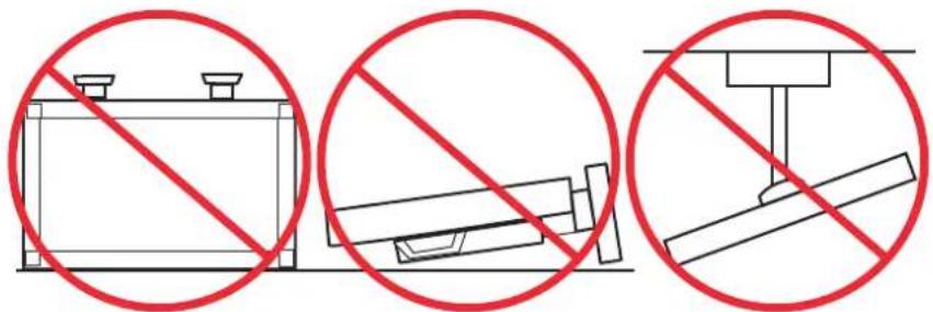
- Do not mount this monitor with any tilt.
- Do not mount this product face up, face down, or upside down for an extended period of time as it may cause permanent damage to the screen.
Ventilation Requirements
When mounting in an enclosed space or recessed area, leave adequate room between the monitor and the enclosure to allow heat to disperse, as shown below.

NOTE: Allow adequate ventilation or provide air conditioning around the monitor, so that heat can properly dissipate away from the unit and the mounting equipment; especially when you use monitors in a multiple screen configuration.
Mounting on ceilings
CAUTION:
- Ensure that the ceiling is strong enough to support the weight of the unit and the mounting equipment over time, against earthquakes, unexpected vibrations, and other external forces.
- Be sure the unit is mounted to a solid structure within the ceiling, such as a support beam. Secure the monitor using bolts, spring lock washers, washer and nut.
- DO NOT mount to areas that have no supporting internal structure. DO NOT use wood screws or anchor screws for mounting. DO NOT mount the unit to ceiling or to hanging fixtures.
Attaching Mounting Accessories
The monitor is designed for use with the VESA mounting system. Be careful to avoid tipping the monitor when attaching accessories.

Mounting accessories can be attached with the monitor in the face down position. To avoid scratching the LCD panel, always place a soft cloth, such as a blanket that is larger than the monitor's screen area, on the table before laying the monitor face down. Make sure there is nothing on the table that can damage the monitor.
When using mounting accessories other than SHARP compliant and approved, they must comply with the VESA Flat Display Mounting Interface Standard (FDMI).
NOTE: Prior to installation, place the monitor face down on a flat even surface that is larger than the monitor screen. Use a sturdy table that can easily support the weight of the monitor.
Using a Wall Mount Adapter
If the mounting accessory interferes with ventilation holes, use the included wall mount adapters (Dia. 14 mm) and screws. If the adapter screws are too long, include a washer to reduce the depth. Washer not included.

NOTE: Pictured mounting accessories may not be available in some countries.
Installing an Option Board
NOTE: Please contact your supplier for available Option Boards.
The Raspberry Pi is not available at this monitor.
- Turn off the main power switch.
- Place the monitor face down on a flat even surface that is larger than the monitor screen. Use a sturdy table that can easily support the weight of the monitor.
NOTE: To avoid scratching the LCD panel, always place a soft cloth, such as a blanket that is larger than the monitor's screen area, on the table before laying the monitor face down. Make sure there is nothing on the table that can damage the monitor.
- Remove the attached slot cover by unscrewing the installed screws (Figure 1), sliding it to the right (Figure 2) and moving it up (Figure 3).
- Insert the Option Board into the monitor and fix it in place with the removed screws (Figure 4). (Recommended Fasten Force: 139 - 189 N·cm).

![graph LR A["Before Battery Inlet"] --> B["Add Air Bag"] B --> C["Add Air Box"] C --> D["Add Air Panel"] D --> E["Add Air Fan Out"] style A fill:#f9f,stroke:#333 style B fill:#ccf,stroke:#333 style C fill:#cfc,stroke:#333 style D fill:#fcc,stroke:#333 style E fill:#cff,stroke:#333](/content/2026/08/1616062/images/cceb0b891dfa74c0c008d0b4843e79e91f95634cfff17de76bf99c5f588a214f.jpg)
Figure 1 Figure 2 Figure 3 Figure 4
NOTE: Unless your monitor is purchased as part of a special bundle package, no Option Boards will be in the box or installed in the monitor. These are optional accessories available for separate purchase. Please contact your supplier for a list of Option Boards available for your monitor.
Make sure the board is inserted into the slot in the correct orientation.
Do not apply excessive force to manipulate the Option Board before fixing it with screws.
WARNING: Ensure the Option Board is securely fastened using the original screws to prevent the Option Board from falling out the monitor. A falling Option Board may expose you to danger.
Installing an Optional Sensor Unit
For installing the sensor to the monitor, please use the double-sided tape as shown below:

You can set the sensor unit on any side of the monitor. Set the sensor unit 8 mm away from the front edge.
Chapter 2 Parts Name and Functions
This Chapter Includes:
→ "Control Panel" on page 16
→ "Terminal Panel" on page 17
→ "Wireless Remote Control (Optional)" on page 19

① Button (power button)
Switches between power on and standby state. See page 30.
② MUTE Button
Switches the audio mute on/off.
③ INPUT/SET Button
INPUT: Cycles through the available inputs when the OSD menu is turned off. See page 23 and page 25.
[DVI], [HDMI1], [HDMI2], [DisplayPort1], [DisplayPort2], [VGA (YPbPr/RGB)], [VIDEO], [MP], [OPTION]*1. These are available inputs only, shown as their factory preset name.
NOTE: MP is an abbreviation of Media Player.
SET: Acts as a set button when making a selection when the OSD menu is open.
*1: This function depends on which Option Board installed in the monitor.
4 ▶ Button
Increases the audio output level when the OSD menu is turned off.
Acts to move the highlighted area to the right when navigating through the OSD menu options.
Acts as plus button to increase the adjustment of an OSD menu option after it has been selected with the [INPUT/SET] button.
OSD is an abbreviation of On-Screen Display.
5 Button
Decreases the audio output level when the OSD menu is turned off.
Acts to move the highlighted area to the left when navigating through the OSD menu options.
Acts as minus button to decrease the adjustment of an OSD menu option after it has been selected with the [INPUT/SET] button.
6 ▲ Button
Activates the OSD menu when the OSD menu is turned off. Acts as up button to move the highlighted area up to select adjustment items within the OSD menu.
7▼ Button
Activates the OSD menu when the OSD menu is turned off. Acts as down button to move the highlighted area down to select adjustment items within the OSD menu.
⑧ MENU/EXIT Button
Activates the OSD menu when the OSD menu is turned off. Acts as a back button within the OSD to move to the previous OSD menu.
Acts as an exit button to close the OSD when on the main menu.
9 Remote Control Sensor and Power Indicator
Receives the signal from the remote control (when using the wireless remote control).
Glows blue when the monitor is in active mode *1 .
Green and Amber blink alternately when the [SCHEDULE SETTINGS] function is enabled *2 .
When a component failure is detected within the monitor, the indicator will blink red or blink a combination of red and blue.
Please refer to the Power ON and OFF table on page 30.
1 : If [OFF] is selected in the [POWER INDICATOR] the LED will not glow when the monitor is in active mode. See page 116.
2 : If [OFF] is selected in the [SCHEDULE INDICATOR], the LED will not blink. See page 116.

① AC IN Connector
Connects with the supplied power cord.
② Main Power Switch
On/Off switch to turn main power ON/OFF.
3 AUDIO IN (AUDIO1/AUDIO2)
Audio signal input from external equipment such as a computer or player.
④ VGA IN (Mini D-Sub 15-pin)
Analog RGB signals input from a personal computer or from other RGB equipment. This input can be used with an RGB or YPbPr source. Please select the signal type in [TERMINAL SETTINGS]. See page 107.
NOTE: When you use this connector for YPbPr, please use a suitable signal cable. If you have any questions, please ask your supplier.
⑤ DisplayPort OUT (DisplayPort OUT (DAISY CHAIN OUT))
Output signal from DisplayPort 1 or OPTION.
⑥ DisplayPort IN (DisplayPort1 (DAISY CHAIN IN)/DisplayPort2))
DisplayPort signals input.
7 HDMI IN (HDMI1 (DAISY CHAIN IN)/HDMI2 (CEC))
HDMI signals input.
⑧ HDMI OUT (HDMI OUT (DAISY CHAIN OUT))
Output signal from HDMI 1, DVI IN, or OPTION.
9 DVI IN (DVI-D)
Digital RGB signals input from a computer or HDTV device having a digital RGB output. See page 107.
NOTE: This connector does not support analog input.
⑩ RS-232C IN (D-Sub 9-pin)
Connect RS-232C input from external equipment, such as a computer, in order to control RS-232C functions. See page 77.
11 REMOTE
Use the optional sensor unit by connecting it to your monitor. See page 14.
NOTE: Do not use this connector unless specified.
⑫ microSD Card Slot (Media Player microSD)
microSD memory card reader for use with the Media Player. See page 37.
To install the microSD card slot cover, please refer to "Installing microSD card slot cover". See page 26.
13 USB Ports
For the USB port information, please see "Connecting a USB Device" on page 28.
USB1 (SENSOR): Downstream port (USB Type-A).
USB2: Upstream port (USB Type-B).
USB CM1 (2A): Power supply port.
USB CM2: Service port. Please do not connect devices.
Media Player USB: USB storage device reader for use with the Media Player.
14 VIDEO IN
Composite video signal input.
15 LAN Port IN/OUT (RJ-45) (LAN1 (DAISY CHAIN IN)/LAN2 (DAISY CHAIN OUT))
Connect to LAN in order to manage and control the monitor over the network. See page 78.
NOTE: Please give priority for use to LAN1.
16 AUDIO
Audio signal output from AUDIO 1/2, DisplayPort and HDMI to an external device (stereo receiver, amplifier, etc.).
NOTE: This connector is not a Headphone terminal.
17 EXTERNAL SPEAKER TERMINAL
Audio signal output.
Red terminal is plus (+).
Black terminal is minus (-).
NOTE: This speaker terminal is for 15 W + 15 W (8 Ω) speaker.
18 Option Board Slot
Slot for installation of a Slot 2 type Option Board. See page 13.
NOTE: Please contact your supplier for a list of compatible Option Boards.
19 Security Slot
Security and theft protection lock slot compatible with Kensington security cables/equipment.
NOTE: For products, visit Kensington's website.
20 Option Speaker Mounting Holes
NOTE: Please contact your supplier for a list of compatible speaker.
21 Optional Sensor Unit (remote control, room light sensing and human sensing)
Receives the signal from the Remote control.
Detects the level of ambient light, allowing the monitor to make automatic adjustments to the backlight setting, resulting in a more comfortable viewing experience.
Do not cover this sensor.
Detects human presence in front of the monitor.
See page 31.
Wireless Remote Control (Optional)

NOTE: The buttons with no explanation are not used with your monitor model.
① POWER ON Button
POWER ON resumes full power from low power mode.
See page 30.
② STANDBY Button
STANDBY puts the monitor in low power mode.
See page 30.
③ INPUT Button
Display "Input" menu.
The button names reflect the factory preset name for the input.
When you press the MEDIA PLAYER button, File Manager opens. Selecting a video, image, or music file will start playback. (See page 13.)
4 KEYPAD
Press the buttons to set and change passwords and set the REMOTE ID. See page 71.
Some buttons are used for CEC (Consumer Electronics Control) and the Media Player function ("Using the Remote Controls" on page 39)
⑤ ENT Button
Makes selections in the Media Player settings.
See page 61.
For use with an Option Board. The function depends on which Option Board installed in the monitor.
6 DISPLAY Button
Shows/Hides the information OSD. See page 35.
Unlocks the remote control's buttons if they have been locked in the IR LOCK SETTINGS. Press and hold the DISPLAY button for more than 5 seconds to unlock the remote. See page 58.
⑦ MENU Button
Opens and closes the OSD menu. See page 35.
8 INPUT Button
Switches the video input with each button press.
The input names reflect the factory preset name for the input unless they are manually renamed in the OSD menu.
EXIT Button
Acts as a back button within the OSD to move to the previous OSD menu.
Acts as an EXIT button to close the OSD when on the main menu.
10 ▲/▼ Button (up/down button)
Acts as navigation buttons, within the OSD and Media Player menus, to move the highlighted area up or down. Moves the Active picture up or down when using Multi Picture Mode. See page 52.
⑪ ◀/▶ Button (left/right button)
Acts as navigation buttons, within the OSD and Media Player menus, to move the highlighted area left or right. Increases or decreases the adjustment level within the selected OSD menu setting.
Moves the Active picture left or right when using Multi Picture Mode. See page 52.
12 SET Button
When the OSD is shown, this button acts as a set button when you make a selection.
⑬ VOL +/- Button
Increases or decreases the audio output level.
14 MUTE Button
Audio is temporarily muted.
Pressing again will return it back to the original volume.
15 PICTURE MODE Button
Select a picture mode.
| PICTURE MODE PURPOSE | |
| HIGH BRIGHT Highest brightness setting. | |
| STANDARD Standard setting. | |
| sRGB | The standard color space used for the Internet, Windows® operating systems and digital cameras.Recommended setting for general color management. |
| CINEMA | A setting that boosts dark tones; best suited for movies. |
| Transportation | Maximum backlight brightness with high contrast to read text under all conditions. |
| CUSTOM Custom setting. | |
16 AUDIO INPUT Button
Selects the audio input source [IN1], [IN2], [HDMI1], [HDMI2], [DisplayPort1], [DisplayPort2], [OPTION]*1, and [MP].
*1: This function depends on which Option Board is installed in the monitor.
17 ASPECT Button
Cycles through the picture aspect ratios [FULL], [WIDE]*, [DYNAMIC]*, [1:1], [ZOOM] and [NORMAL]. See page 33.
*: HDMI1, HDMI2, VGA (YPbPr) inputs only.
18 STILL Button
ON/OFF button: Activates/deactivates still picture mode.
CAPTURE button: Captures a still picture.
NOTE: • This function deactivates when selecting [MULTI PICTURE MODE], [TEXT TICKER], [SCREEN SAVER], [POINT ZOOM], [IMAGE FLIP except for NONE], [SUPER in INPUT CHANGE], [TILE MATRIX].
- [CLOSED CAPTION] is not available when STILL is active.
- If the input signal is option, this button's action depends on which Option Board is installed in the monitor.
19 ACTIVE PICTURE Button
Selects the active picture when Multi Picture Mode is enabled. See page 52.
20 MULTI PIC. Button
ON/OFF button: Turns Multi Picture Mode on and off.
MODE button: Switches the mode between PIP (Picture-In-Picture) and PBP (Picture-By-Picture).
CHANGE button: Swaps the selected inputs between Picture 1 and Picture 2.
PICTURE ASPECT button: Selects the active picture frame aspect.
For more information see page 52.
NOTE: If you press SET button while Multi Picture is ON, you can change the active picture's picture size.
21 REMOTE ID Button
Activates the REMOTE ID function. See page 71.
22 IMAGE FLIP Button
Toggle switches between [H FLIP], [V FLIP], [180° ROTATE] and [NONE]. See page 102.
23 OPTION MENU / GUIDE / MTS
For use with an Option Board. The function depends on which Option Board is installed in the monitor.
24 CH -/+ Button (ZOOM -/+)
Increases or decreases the point zoom level. Please refer to the Point Zoom instructions. See page 34.
25 Button*
Activates closed captioning for VIDEO input only.
*: When using with an Option Board, the function depends on which Option Board is installed in the monitor. Refer to the Option Board's user's manual for further information.
This Chapter Includes:
→ "Wiring Diagram" on page 22
→ "Connections" on page 22
→ "External Video Connections" on page 23
→ "Internal Video Sources" on page 25
→ "Connecting a USB Device" on page 28
Connecting External Equipment
NOTE: Do not connect or disconnect cables when turning on the monitor's main power or other external equipment's power as this may result in loss of image.
- Do not use an attenuating (built-in resistor) audio cable. Using an audio cable with a built-in resistor will lower the sound level.
Before making connections:
- Turn off the device's power before connecting it to the monitor.
- Refer to the device's user manual for available connection types and instructions for the device.
- We recommend turning off the monitor's main power before connecting or disconnecting a USB storage device or microSD memory card to avoid data corruption.
Wiring Diagram
![graph TD A["Computer (USB)*"] --> B["USB port (Type-A)"] A --> C["USB port (Type-B)"] B --> D["Stereo Amplifier"] C --> D D --> E["VCR Player or DVD Player (Video)"] E --> F["AV Amplifier"] E --> G["HDMI video player or Computer (HDMI)"] F --> H["Blu-ray or DVD Player (HDMI)"] G --> I["HDMI 1 (DAISY…](/content/2026/08/1616062/images/8e6d2c5d19f7668fd209a9f0332ca1029dd8272d4c02bea660f2f9b416be2938.jpg)
*: Multiple monitors that are daisy-chained have a limit to the number of connectible monitors. See page 68.
*1: The device connected to USB2 can control the device connected to USB1 (SENSOR). See the "Connecting a USB Device" on page 28.
Connections
| Connecting terminal | Setting in TERMINAL SETTINGS | Input signal name Connecting audio terminal | Input button in remote control | |
| DVI (DVI-D) DVI MODE: DVI-PC/DVI-HD DVI IN1/IN2 DVI | ||||
| HDMI1 (DAISY CHAIN IN) VIDEO LEVEL: RAW/EXPAND* 2 | HDMI1 HDMI1 HDMI1 | |||
| HDMI2 (CEC) VIDEO LEVEL: RAW/EXPAND* 2 | HDMI2 HDMI2 HDMI2 | |||
| DisplayPort 1 (DAISY CHAIN IN) VIDEO LEVEL: RAW/EXPAND* 2 | DisplayPort 1 DisplayPort 1 DisplayPort 1 | |||
| DisplayPort 2 | VIDEO LEVEL: RAW/EXPAND* | DisplayPort 2 DisplayPort 2 DisplayPort 2 | ||
| VGA (RGB, YPbPr) | VGA MODE: RGB/YPbPr | VGA: RGB/YPbPr | IN1/IN2 | VGA (RGB/YPbPr) |
| VIDEO | — | VIDEO | IN1/IN2 | VIDEO |
| Option Board Slot (SLOT2) | VIDEO LEVEL: RAW/EXPAND* | OPTION | OPTION (ANALOG/DIGITAL)* | OPTION |
| Media Player USB/microSD | — | MP | Media Player USB/microSD | MEDIA PLAYER |
√2: Please set appropriate setting for input signal.
Video Inputs
- Composite Video (RCA) – Analog video signal input with standard definition video quality, no audio signal.
- VGA – Analog video signal connection to a computer. Video only, no audio signal.
- DVI-D – Digital video signal connection to a computer. Video only, no audio signal.
- HDMI – High definition digital video and audio signal connection to a computer, streaming media player, Blu-ray player, game console, etc.
- DisplayPort (DP) – High definition digital video and audio signal connection to a computer.
Connecting to a Personal Computer
The type of video connections that can be used to connect to a computer depends on the computer's display adapter.
The following table shows the typical factory preset signal timing for each connection type. Some display cards may not be able to support the required resolution for proper image reproduction with the selected connection. The monitor will show the proper image by automatically adjusting the factory preset timing signal.
| Resolution | Scanning frequency | VGA DVI MODE2 1.1a 1.2 | HDMI DisplayPort | Remarks | |||||
| Horizontal Vertical MODE1 | |||||||||
| 640 x 480 | 31.5 kHz | 60 Hz | Yes | Yes | Yes | Yes | Yes | Yes | |
| 800 x 600 | 37.9 kHz | 60 Hz | Yes | Yes | Yes | Yes | Yes | Yes | |
| 1024 x 768 | 48.4 kHz | 60 Hz | Yes | Yes | Yes | Yes | Yes | Yes | |
| 1280 x 720 | 45.0 kHz | 60 Hz | Yes | Yes | Yes | Yes | Yes | Yes | |
| 1280 x 768 | 47.8 kHz | 60 Hz | Yes | Yes | Yes | Yes | Yes | Yes | |
| 1280 x 800 | 49.7 kHz | 60 Hz | Yes | Yes | Yes | Yes | Yes | Yes | |
| 1280 x 960 | 60.0 kHz | 60 Hz | Yes | Yes | No | No | No | No | |
| 1280 x 1024 | 64 kHz | 60 Hz | Yes | Yes | Yes | Yes | Yes | Yes | |
| 1360 x 768 | 47.7 kHz | 60 Hz | Yes | Yes | Yes | Yes | Yes | Yes | |
| 1366 x 768 | 47.7 kHz | 60 Hz | Yes | Yes | Yes | No | Yes | Yes | |
| 1400 x 1050 | 65.3 kHz | 60 Hz | Yes | Yes | Yes | Yes | Yes | Yes | |
| 1440 x 900 | 55.9 kHz | 60 Hz | Yes | Yes | Yes | Yes | Yes | Yes | |
| 1600 x 1200 | 75.0 kHz | 60 Hz | Yes | Yes | Yes | Yes | Yes | Yes | Compressed image |
| 1680 x 1050 | 65.3 kHz | 60 Hz | Yes | Yes | Yes | Yes | Yes | Yes | |
| 1920 x 1080 | 67.5 kHz | 60 Hz | Yes | Yes | Yes | Yes | Yes | Yes | Recommended resolution |
| 1920 x 1200 74.6 kHz 60 Hz | Yes* | 1 | Yes* 1 | Yes | Yes | Yes | Yes | Compressed image | |
| 3840 x 2160 | 65.7 kHz | 30 Hz | No | No | No | No | Yes | Yes | Compressed image |
| 3840 x 2160 | 67.5 kHz | 30 Hz | No | No | Yes | Yes | No | No | Compressed image |
| 3840 x 2160 | 133.3 kHz | 60 Hz | No | No | No | No | No | Yes* | Compressed image |
| 3840 x 2160 | 135.0 kHz | 60 Hz | No | No | No | Yes | No | No | Compressed image |
| 4096 x 2160 | 54.0 kHz | 24 Hz | No | No | Yes | Yes | No | No | Compressed image |
*: Only HBR2 is set.
*1: Reduce blanking.
Connecting to a Computer with HDMI
- Please use an HDMI cable with the HDMI logo.
- It may take a moment for the signal to appear after turning on the computer.
- Some display cards or drivers may not display an image correctly.
- When you use a computer with HDMI, please set [OVERSCAN] to [AUTO] or [OFF] as display drivers may not be fully compatible and may not display an image correctly. See page 101.
- To output HDMI audio, set [HDMI1] or [HDMI2] at AUDIO INPUT in the OSD or choose [HDMI1] or [HDMI2] by pressing the remote control AUDIO INPUT button.
- If the source signal is 3840 x 2160 (60 Hz) or HDCP 2.2 or HDR, please set [MODE2] at [HDMI] in [TERMINAL SETTINGS]. See page 107.
- If the monitor's main power is turned on after a connected computer is turned on, sometimes an image is not displayed. In this case, please turn off the computer then turn it on again.
Connecting a Computer with DisplayPort
- Please use a DisplayPort cable with the DisplayPort compliance logo.
- To use the DisplayPort out connector, please refer to Video out. See page 70.
- It may take a moment for the signal to appear after turning on the computer.
- When connecting a DisplayPort cable to a component with a signal conversion adapter, an image may not appear.
- Some DisplayPort cables feature a locking function. When removing this cable, hold down the top button to release the lock.
- To output DisplayPort audio, set [DisplayPort1] or [DisplayPort2] at [AUDIO INPUT] in the OSD or choose [DisplayPort1] or [DisplayPort2] by the remote control AUDIO INPUT button.
- To display individual images at each connected monitors with the DisplayPort OUT connector, please set [DisplayPort1.2] and [MST] at [DisplayPort] in the [TERMINAL SETTINGS]. See page 107.
- If the monitor's main power is turned on after a connected computer is turned on, sometimes an image is not displayed. In this case, please turn off the computer then turn it on again.
Connecting to a Media Device with HDMI
Connect using a single HDMI cable for the highest picture and audio quality from Blu-ray players, streaming media players, or game consoles. 4K UHD content is displayed when the connected media player also supports 4K content.
Supports HDCP (High-bandwidth Digital Contents Protection) coding, a type of digital rights management that prevents high-definition content, in Blu-ray discs, DVDs and streaming media, from being copied or broadcast illegally.
NOTE: • Supports 1920x1080 (60 Hz), 1080p, 1080i, 720p@50Hz/60Hz, 576p@50Hz, 480p@60Hz, 576i@50Hz, 480i@60Hz, 3840x2160 (30Hz/24Hz/25Hz [MODE1]), 3840x2160 (60Hz [MODE2]), 4096x2160 (24Hz).
- Connect the HDMI cable when both the media player and the monitor are powered off.
- Use an HDMI cable with the HDMI logo.
- Some HDMI cables and devices may not display an image correctly due to different HDMI specifications.
HDMI-CEC provides compatible media players, connected via HDMI, the ability to communicate and allow limited control between the device and the monitor. For example, turning on a Blu-ray player can immediately switch input to the Blu-ray player without using the remote control. Not all devices are fully compatible, and, in some cases, the media device manufacturer may only provide compatibility with its own monitors or TVs. See “Supporting HDMI CEC Command” on page 76.
When supported, the monitor's optional Remote Control can be used to control the HDMI media device. The remote's CEC enabled buttons are:
1 ( ), 2 ( ), 3 ( ), 5 ( ) 6 ( ) , ENT, EXIT, , , ,
NOTE: The instructions in this section guide you through configuring [CEC] in the monitor's OSD menu. These settings can also be configured using the monitor's web controls. The function names and location in the web controls are the same as the OSD menu.
Enabling CEC
- Connect a CEC device to the HDMI2 port.
Press the HDMI2 button on the remote control.
- Press the MENU button to open the OSD.
- Navigate to [CONTROL] then to [CEC].
- Select [ON] for [CEC] then [YES] for the [AUTO TURN OFF] and [AUDIO RECEIVER].
- Select [YES] under [SEARCH DEVICE].
When the search is complete, the HDMI port with a CEC connected device is displayed with its name.
If no CEC device is found, make sure the device is plugged in, turned on, it supports CEC and CEC is enabled. Depending on the manufacturer, the CEC feature may have a different name. Refer the device's product manual.
- Press the EXIT button on the remote control.
Internal Video Sources
There are some video sources available that are internal and not connected to the video ports on the monitor's Terminal Panel. These video sources are:
- Media Player
- OPS Option Board
Media Player
The internal Media Player will play audio and video files that are stored on a microSD memory card or USB storage device. See page 37 for instructions on using the Media Player.
Connect Compatible microSD Memory Card
Format a microSD memory card in the FAT32 format or FAT16 format. Refer to the computer's instruction manual or help file on how to format a microSD memory card.
NOTE: Up to 32GB microSDHC is supported.
The monitor is not guaranteed to work with all microSD memory cards sold commercially.
microSD with CPRM is not supported.
microSD UHS-1 or UHS-2 are not supported.
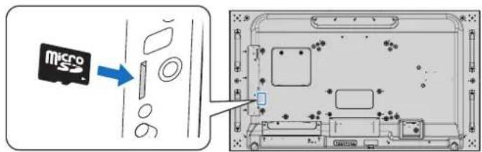
- When inserting a microSD memory card, please make sure of the microSD memory card is in the correct direction then insert it. Fully insert the microSD memory card and press in until the spring lock is engaged.
- When ejecting a microSD memory card from the microSD card slot, press the center of the microSD memory card to release the spring lock, then take it out.
Installing microSD card slot cover
To secure your microSD memory card, we recommend you to install the microSD card slot cover.
Please insert the edge of the microSD card cover into the hole. Secure it in place with the provided screw.

microSD card cover is installed.Hole
Connect Compatible USB storage device
Format a USB storage device in the FAT32 format or FAT16 format to use it with the Media Player. Refer to the computer's instruction user's manual or Help file on how to format a USB storage device.
Please use a USB storage device with this monitor in accordance with the drawing below.
If the physical size of the USB storage device is larger than the supported size listed below, please use a USB extension cable.

NOTE: • If the monitor does not recognize a connected USB storage device, make sure the file structure is FAT32 or FAT16.
- The monitor is not guaranteed to work with all USB storage devices sold commercially.
- Insert the USB storage device into the Media Player USB port on the monitor's side terminal panel.
- The Media Player does not use any other USB connection on the monitor (see page 17).
Option Boards for the Monitor
When an Option Board is installed in the monitor, it will show as available in the list in the [INPUT] of the OSD menu.
Option Boards are available separately and must be physically installed in the monitor.
This document contains instructions for how to use the monitor without any additional options.
The location where an Option Board is installed is indicated on the Terminal Panel diagram (see page 17).
NOTE: • Please contact your supplier for available Option Boards.
Connecting a USB Device
Some of the USB ports on the monitor's terminal panel have different uses depending on the type of connected USB device. Please follow these guidelines when using these ports with supported devices.
USB1 (SENSOR): USB downstream port (Type-A).
Connection used by external USB devices (such as cameras, flash memory, keyboards, etc.) and internal devices (an Option Board when installed).
USB2: USB upstream port (Type-B).
Connection to a computer with a USB cable. A USB compatible computer connected to USB2 can control the devices connected to USB1 (SENSOR) port.
USB CM1 (2A): Power supply port.
Provides up to 2 A of power to a connected USB device, such as HDMI streaming media or presenter sticks. The actual amount of power consumption depends on the connected device. Make sure to use a USB cable that supports 2 A.
Enable [USB POWER] in the [USB] settings of the [CONTROL] menu in the OSD. See page 117.
Please refer to the specifications pages for power supply information. See page 92.
USB CM2: Service port.
Please do not connect devices.
Media Player USB: USB downstream port (Type-A).
This port is for future software upgrades.
USB storage device reader for use with the internal Media Player. See page 37.
CAUTION: Do not bind the USB cable. It may trap heat and start a fire.
NOTE: • Please make sure the connector shape and orientation is correctly aligned when connecting the USB device or cable.
- Depending on the computer BIOS, OS or device, the USB function may not work. Please check the user's manual of your computer or device.
- Before turning off the main power switch of the monitor or shutting down Windows ® , please turn off the USB function and remove the USB device from the monitor. Data may be lost or corrupted if the USB device is not disconnected properly.
- It may take a few seconds for the monitor to recognize the USB input. Do not disconnect the USB cable or disconnect and reconnect the USB cable before the monitor recognizes the input.

Chapter 4 Basic Operation
This Chapter Includes:
→ "Power ON and OFF" on page 30
→ "Operating Range for the Optional Remote Control" on page 31
→ "Using Power Management" on page 31
→ "Showing the Information OSD" on page 32
→ "Switching Between Picture Modes" on page 32
→ "Setting the Aspect Ratio" on page 33
→ "Using Point Zoom" on page 34
→ "OSD (On-Screen-Display) Controls" on page 35
→ "Using the Media Player" on page 37
Power ON and OFF
Press the button on the Control Panel or POWER ON button on the Remote Control to turn on the monitor.
The monitor's power LED indicates the current status of the monitor. Please refer to the following table for information about the LED indicator.
| LED indicator status and lighting pattern | Condition Recovery | |
| Glowing blue Normal 1. Turn on the monitor by | the remote control or the monitor button.2. Send an AV signal input to the monitor. | |
| Blinking green*2 | Under any of the conditions below, no input signal has been detected by the monitor during the period of time*1 you set:[OPTION POWER] is [ON] or [AUTO] then an Option Board is connected.[OPTION POWER] is set to [ON].[CEC] is set to [MODE 1] or [MODE 2].[DisplayPort VERSION] is set to [1.2 MST].[AUTO INPUT CHANGE] is set to a setting except for [NONE].[USB POWER] is set to [ON]. | |
| Glowing amber*2(Networked standby mode) | When 10 sec have passed without meeting the conditions of blinking green, when the monitor recognizes the LAN connection and a certain period of time has passed without selected signal input. | |
| Blinking amber*2(Standby mode) | When 3.5 min have passed without the conditions of blinking green, when a certain period of time has passed without the monitor recognizing the LAN connection and selecting the signal input. | |
| Glowing red Turn off the monitor by the remote control or the monitor button. Turn on the monitor by the remote control or the monitor button. | ||
*1: Time setting for auto power save is available at [POWER SAVE] (See page 112).
*2: [POWER SAVE] is set to [ENABLE].
NOTE: • The blue LED indicator that the monitor is powered on and functioning normally can be turned off in the monitor's OSD menu options. See page 116.
- If the indicator is blinking red in a combination of long and short durations, a certain failure might have occurred, please contact your supplier.
The Main Power switch must be in the ON position in order to power up the monitor using the POWER ON button on the remote control or the ⏻ button on the Control Panel.


Off mode, when main power is off.
Operating Range for the Optional Remote Control
Point the top of the remote control toward the monitor's remote control sensor during button operation.
Use the remote control within a distance of about 7 m (23 ft.) from the remote control sensor, or at a horizontal and vertical angle of within 30° and within a distance of about 3.5 m (10 ft.).
NOTE: The remote control system may not function when direct sunlight or strong illumination strikes the remote control sensor, or when there is an object in the path.
Handling the remote control
- Do not expose to strong shock.
- Do not allow water or other liquid to splash on the remote control. If the remote control gets wet, wipe it dry immediately.
- Avoid exposure to heat and steam.
- Except to install the batteries, do not open the remote control.

Using Power Management
This monitor follows the VESA approved DPM (Display Power Management) function. This function decreases the power consumption of the monitor when it is not in use.
When connected to a computer, power consumption by the monitor reduces automatically if the keyboard or mouse are not used during the time set in the computer's power management settings. Refer to your computer's user manual for more information.
When connected to an AV source, such as a Blu-ray, DVD, or streaming video player, power consumption by the monitor reduces automatically after a certain amount of time has passed since the monitor recognized "no signal input". This option is turned on or off in the [POWER SAVE] settings under the [PROTECT] menu of the OSD. See page 112.
NOTE: • Depending on the computer and display card used, this function may not operate.
- After the video signal is lost, the monitor automatically goes into off at a preset time period. Please refer to the [AUTO POWER SAVE TIME SETTING] in [POWER SAVE] page 112.
- Schedules can be created for the monitor to power on or off at specific times. See page 44.
Menu item details
The settings below are recommended settings and conforms to the “Normal Configuration” as defined in the EcoDesign Regulation (2019/2021).
- INPUT DETECT : NONE
- DisplayPort - 1.2 : SST
- TILE MATRIX ENABLE : NO
- POWER SAVE : ENABLE
• HUMAN SENSING : DISABLE - USB POWER : AUTO
- CEC : OFF
• OPTION POWER : OFF
Showing the Information OSD
The Information OSD provides information such as: Input Source, Picture Size, IP Address, Monitor ID, etc.
Press the DISPLAY button on the remote control to bring up the Information OSD.

Switching Between Picture Modes
Press the PICTURE MODE button on the wireless remote control to cycle through the SpectraView Engine picture modes from 1 to 5.
The picture modes are pre-configured with settings for general use. See “Advanced Color Adjustment” on page 45 for instructions on changing the picture mode settings.
Setting the Aspect Ratio
Press the ASPECT button on the remote control to cycle through the options available for the current input signal.
For MP (Media Player), VIDEO
• FULL → ZOOM → NORMAL
For DVI, DisplayPort1, DisplayPort2, VGA (RGB), OPTION*1
• FULL → 1:1 → ZOOM → NORMAL
*1 : This function depends on which Option Board is installed in the monitor.
For VGA (YPbPr), HDMI1, HDMI2
• FULL → WIDE → DYNAMIC → 1:1 → ZOOM → NORMAL
| Aspect ratio of image | Unchanged view*2 | Recommended selection for picture aspect*2 | Description | |
| 4:3 |  | [NORMAL] Repurises the aspect  | ratio that is sent from the source. | |
| [DYNAMIC] |  | Expands a 4:3 picture to fill the entire screen with non-linearity. Some of the outside image area will be cut off due to expansion. | ||
| Squeeze |  | [FULL] Fills the | 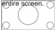 | |
| Letterbox |  | [WIDE] Expand | 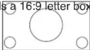 | signal to fill the entire screen. |
*2. Gray areas indicate unused portions of the screen.
1:1: Shows the image in a 1 by 1 pixel format.
ZOOM
- The zoom function increases the image size, which expands the image beyond the active screen area. The parts of the image outside the active screen area are not shown.

Using Point Zoom


The [POINT ZOOM] function increases the image size and expands it horizontally and vertically simultaneously. The image can be increased up to 10 times its size.
- Press the SET button on the remote control. A magnifier icon appears on-screen.
- Move the magnifier to the area of the image you want to focus on by pressing the ▲▼▶◀ buttons.
- Press the CH+ button to zoom in. Press CH- button to zoom out. When zooming in, the image expands passed the active screen area. The area at the magnifier location shifts closer to the center of the screen at each magnification level.
- Press the SET button to close the magnifier.
- The image will remain zoomed in after closing the magnifier. Press the EXIT button to return to the normal image size.
NOTE: • The image may look distorted when using this function.
- [POINT ZOOM] is not available when the OSD settings are enabled for [IMAGE FLIP] (except for NONE), [MULTI PICTURE MODE], [SCREEN SAVER], [SUPER] in [INPUT CHANGE], [CLOSED CAPTION], [TILE MATRIX] and [TEXT TICKER].
- When the [ASPECT] setting is [DYNAMIC] or [ZOOM], pressing the SET button automatically sets the [ASPECT] to [FULL] and then starts the [POINT ZOOM] function.
- After exiting [POINT ZOOM], the [ASPECT] will return to the previous [ASPECT] setting. When the [ASPECT] is changed during the [POINT ZOOM] operation, [DYNAMIC] and [ZOOM] will be set to [FULL].
- The magnifier icon will not move outside the active picture area.
- The image returns to the normal size after changing the input signal or when the monitor is powered off.
- [POINT ZOOM] deactivates if the [ASPECT] changes while using the [POINT ZOOM] function.
- The [STILL] function is not available when [POINT ZOOM] is active.
- [POINT ZOOM] is not available with a 3840 x 2160 (60 Hz) DisplayPort signal.
- When [HDMI] of the [TERMINAL SETTINGS] is set to [MODE2], [POINT ZOOM] is not available.
OSD (On-Screen-Display) Controls
NOTE: Some functions may not be available depending on the model or optional equipment.

![graph LR A["Remote Control"] --> B["Press SET to select an option."] B --> C["Press SET to select the function or setting to be adjusted."] C --> D["Press MENU or EXIT."]](/content/2026/08/1616062/images/afb76398dd870c125b82a8d957856dddaa04d1f04e789bd07802392a9b1038d9.jpg)

Below is a brief summary of where controls are under each menu item. A table listing all options is located in "OSD Controls List" on page 97.
INPUT: Select the input signal source.

PICTURE: Select one of the default picture modes, manually adjust the color settings, enable or disable SpectraView Engine, and adjust the aspect ratio, image flip, and rotation.

AUDIO: Adjust volume, balance, equalizer, input source, and multi-picture mode output.

SCHEDULE: Create auto power on/off schedules, set holidays and week day/weekend schedules, set the date and time, daylight savings time, and auto-off.

MULTI-INPUT: Select Picture-In-Picture and Picture-By-Picture settings, signal input detection, and connection terminal settings.

OSD: Select options related to the on-screen display menu, such as language, the amount of time the OSD stays on-screen, the location of the menu, transparency, rotation, etc.

MULTI-DISPLAY: Set the monitor's monitor ID, configure settings for multi-monitor setup.

PROTECT: Select options related to protecting the monitor hardware, such as configuring the cooling fans, adjusting automatic power save and power on delay, enabling the screen saver and alert mail to be notified when an error occurs in the monitor.

CONTROL: Set network information, security, power, etc.

OPTION: Select settings related to an Option Board if installed.

SYSTEM: View the monitor information (model, serial number, carbon footprint), firmware version, mac address, or perform a factory reset.
Using the Media Player
The internal Media Player will play image and video files that are stored on a microSD memory card or USB storage device. The Media Player plays videos, still images and background music (BGM). See page 28 for instructions on connecting USB storage device or microSD memory card.
Change to the Media Player by pressing the MEDIA PLAYER button on the optional remote control, or select the MP input in the OSD menu [INPUT].
Use the ▲▼▶◀ and SET buttons on the remote control to navigate the Media Player menus.
The screen's "+" corresponds to the ▶ button, and the screen's "-" corresponds to the ◀ button.
Media Player Home Screen

| SETTINGS | Displays the options for configuring the Slideshow, Auto Play, and open the Network Settings screen. See page 61. | |
| MP NETWORKS Displays the options for configuring the Network and Shared Folder settings. | ||
| CONTENTS COPY | Displays the options for copying content to a microSD memory card connected to the monitor. | |
| SD CARD Displays the file list for a connected microSD memory card.(This is a color icon when a microSD memory card is connected and the file system can be read. If this icon is gray, the Media Player does not detect, or it is not able to read, a microSD memory card.) | ||
| USB Displays the file list for a connected USB storage device.(This is a color icon when a USB storage device is connected and the file system can be read. If this icon is gray, the Media Player does not detect, or it is not able to read, a USB storage device.) | ||
NOTE: • If Media Player contents are played while [TILE MATRIX] is active, the image play timing may have a time delay between monitors.
- If the monitor is used in portrait orientation when playing still image files (pictures), please set [OSD ROTATION] to [PORTRAIT]. Image orientation is changed according to what you set at [OSD ROTATION].
- If the monitor is used in portrait orientation when playing videos, the videos are not automatically rotated when you set the [OSD ROTATION] to [PORTRAIT]. Please play video files that are rotated anticlockwise 90° for them to be viewed in the correct orientation.
- A screen will appear when you press one of the monitor control panel buttons while in the Media Player. You can select to control either the OSD menu or the Media Player from the control panel buttons.

| DISPLAY MENU This icon appears on the left side of the Media Player home screen after choosing to control the [MEDIA PLAYER] in the [KEY CONTROL SELECT] screen. Navigate to this icon and press INPUT/SET to stop controlling the Media Player from the monitor button controls. |

| RETURN Goes back one level higher. | |
| PAGE UP Displays the previous set of files in the folder. | |
| PAGE DOWN Displays the next set of files in the folder. | |
| SETTINGS Shows the settings screen for configuring the Media Player. | |
| THUMBNAILS/ICON Switches between displaying thumbnails or icons for files. | |
| SORT Changes the file display order to sort by name (filename), type (file extension), date (date of creation), or size (file capacity). The default sorting order is by “Name”. | |
| EJECT Unmount the USB storage device or the microSD memory card. Please select EJECT when the file list is displayed. | |
| ENT Button (remote control) Select or deselect individual items, such as files to include in the [SLIDESHOW], or a folder to use for [AUTO PLAY] and [PRESET CONTENTS]. |
NOTE: • A maximum of 300 items can be displayed in a folder, including folder icons.
- The maximum folder hierarchy that can be shown is 16 levels.
- Files in which the media type cannot be determined are indicated by a “?” icon.
- Thumbnails may not be able to be displayed for some media types of media files.
Playing Files
Use the ▲ ▼ ▶ ◀ and SET buttons on the remote control to navigate the Media Player menus.
- Select either [SD CARD] or [USB] to view the file list.
- De-select the files you do not want in the slideshow.
All files in the directory are selected by default. Navigate to a file and press the button on the remote to deselect it.
- Navigate to the first file you want to display then press the SET button on the remote control.
This starts the manual slideshow and the selected file will be displayed on-screen. To change the image press the 3m button on the remote control to display the next file in the directory. The images are displayed in the file sort order.
NOTE: The slideshow can be configured to automatically switch images. See page 40.
Using the Remote Controls
| Skips to the previous video file or image file in the current folder. | |
| Starts the video or slideshow from the selected file.Resumes the video or slideshow after pause.Resumes the video from rewind or fast forward. | |
| Skips to the next video file or image file in the current folder. | |
| Stops the video or slideshow. | |
| Pauses the video or slideshow. | |
| Reverses through a video file until the Play, Pause or Stop button is pressed. | |
| Forwards through a video file until the Play, Pause or Stop button is pressed. |
Changing the Side Border Color
The color of the border that appears on the sides of an image, when it does not fill the entire screen, can be changed in the OSD menu settings.
- Press the MENU button on the remote control to bring up on the OSD menu.
- Navigate through the OSD menu to [DISPLAY PROTECTION] → [SIDE BORDER COLOR] then press SET button.
- Move the slider left or right using the ▶ and ◀ buttons on the remote control. The color can be adjusted between 0 (black) and 100 (white).
- Press EXIT button to close the OSD menu.
Use the ▲ ▼ ▶ ◀ and SET buttons on the remote control to navigate the Media Player menus.
- Navigate to the SETTINGS icon and press SET button.
- Navigate to [PLAY MODE] and press SET button.
- Select [AUTO] and press SET button.
- Navigate to [INTERVAL] then use the [▶] and [◀] buttons on the remote to adjust the amount of time an image is displayed before switching.
This setting can be adjusted between 5 and 300 seconds.
-
Configure additional settings as needed.
-
To have the slideshow repeat after the last file in the folder is displayed, press the down arrow and press SET button to select [REPEAT].
- To have background music play while showing still images, press the down arrow and press SET button to show the audio file screen. Navigate to the location where the audio file is saved, select the audio file you want to play and then press SET button. This will immediately return to the [MEDIA PLAYER SETTINGS] screen.
Press the down arrow and press SET button to select BGM. If BGM does not have a check mark next to it, the audio file you selected will not play.
- To choose what should happen when the slideshow is not set to [REPEAT], press the down arrow to [PLAY END SCREEN] then press SET button. Highlight the option you want and press SET button.
- BLACK SCREEN – when the last file is played, a black screen is shown until the 5 button on the remote is pressed.
- FILE LIST – the Media Player returns to the file list screen.
-
SAVE LAST SCREEN – the slideshow pauses on the last screen, the image is displayed until the 5 button on the remote is pressed.
-
Navigate to [OK] and press SET button to save the changes and return to the [MEDIA PLAYER] home screen.
NOTE: • When the slideshow is running, the images are displayed in the files "sorted" order.
If there is a mix of both video files and still image files, the files will still play in the sorted order. The still images will be displayed, when it gets to a video file it will play the video, when the video is done the next still image file will be displayed.
- If an audio file is playing as background music for still image files, the music will stop when a video file is playing, then start again when it returns to displaying still image files.
Use the ▲ ▼ ▶ ◀ and SET buttons on the remote control to navigate the Media Player menus.
- Navigate to the [SETTINGS] icon and press SET button.
- Navigate to [AUTO PLAY] and press SET button.
- Select [SLIDESHOW] and press SET button.
The menu automatically returns to the MEDIA PLAYER SETTINGS screen when pressing SET button on the remote control.
- Navigate to [FOLDER] and press SET button.
- Select either [SD CARD] or [USB].
This depends on which device you have connected that contains the slideshow files.
- Press ENT button the remote control to select the root directory of the microSD memory card or USB storage device.
If the files are in a sub-folder, press SET button on SD CARD or USB, navigate to the folder that contains the slideshow pictures, and then press ENT button on the remote control.
The menu automatically returns to the [MEDIA PLAYER SETTINGS] screen when pressing ENT button on the remote control.
- Navigate to [OK] and press SET button to save the changes and return to the [MEDIA PLAYER] home screen.
Auto play automatically plays any pictures or videos in the selected folder. The images and videos will be displayed in the "sorted" order.
When [AUTO PLAY] is enabled, the monitor will start auto play as follows:
- When powering on the monitor with a USB storage device or microSD memory card already connected, and Media Player was the input source at the last power off.
- When connecting a USB storage device to the Media Player USB (see page 28) port, with the monitor already powered ON and the Media Player home screen displayed.
- When inserting a microSD memory card to the microSD card slot (see page 26), with the monitor already powered ON and the Media Player home screen displayed.
NOTE: • Connecting a USB storage device or microSD memory card with the monitor already powered on is not recommended.
To prevent damage to the monitor and possible corruption of the connected device's data files, the monitor's main power switch should be off before making connections.
- Only one USB storage device can be recognized with this monitor. External hub is not supported with this monitor.
Still Images — Supported formats
| File extension Supported | |
| .jpg, .jpeg, .jpe Baseline | Progressive, RGB, CMYK |
| .png | Interlace, a channel |
Motion Images — Supported formats
| File extension Video codec | Audio codec | |
| .mpg, .mpeg MPEG1, MPEG2 | MPEG Audio Layer3 | (Abbreviation: MP3) AAC-LC (Abbreviation: AAC),LPCM |
| .wmv H.264, WMV MP3, | WMV Standard, WMA 9/10 | Professional |
| .mp4 H.264 MP3, AAC | ||
| .mov H.264 MP3, AAC |
BGM (Background Music) — Supported formats
| File extension Audio codec | |
| .wav LPCM | |
| .mp3 MP3 |
Additional Information
| Item Conditions | ||
| Resolution JPEG | Up to 5000 | x 5000 |
| PNG | Up to 4000 x 4000 | |
| MPEG1 | 480@30fps | |
| MPEG2 | MP@ML, MP@HL, 1080p@30fps / 1080i@60fps | |
| H.264 | High profile Lv.4.2, 1080p@30fps / 1080i@60fps | |
| WMV | Advanced@L3, Simple&Main | |
| Video bit date | - | Up to 15 Mbps |
| Audio sampling rate | - | Up to 48 kHz |
| Audio bit rate | MP2 Up to 384 Kbps | |
| MP3 Up to 320 Kbps | ||
| AAC Up to 1440 Kbps | ||
NOTE: • Some files may not play correctly even when they meet the conditions listed.
- Depending on bit date of the file, the type of USB storage device or microSD memory card you use, it may not play correctly.
- DRM (Digital Right Management) protected files cannot be played.
• The maximum resolution for video files is 1920 (Horizontal) x 1080 (Vertical).
Chapter 5 Advanced Operation
This Chapter Includes:
→ "Creating a Power Schedule" on page 44
→ "Advanced Color Adjustment" on page 45
→ "Multi-Picture Mode" on page 52
→ "Setting Security and Locking the Monitor Controls" on page 56
→ "Media Player Settings" on page 60
The schedule function allows the monitor to automatically change between power on and standby states at different times.
To program the schedule:
- Enter the [SCHEDULE] menu.
① Highlight [SCHEDULE SETTINGS] using the ▲ and ▼ buttons.
② Press the SET or the ▶ button to enter the Settings menu.
③ Highlight the desired schedule number and press SET button.
④ The box next to the number will turn yellow. The schedule can now be programmed.
- Use the ▼ button to highlight the [POWER]. Use the ▶ and ◀ buttons to set [ON].
To set a power off schedule, set [OFF].
- Use the ▼ button to highlight the [TIME]. Use the ▶ and ◀ buttons to set the time.
- Use the ▲ and ▼ buttons to highlight [INPUT]. Use the ▶ and ◀ buttons to choose the input source.
- Use the ▲ and ▼ buttons to highlight [PIC. MODE]. Use the ▶ and ◀ buttons to choose the picture mode.
- Use the ▼ button to select [DATE], [EVERY DAY], [EVERY WEEK], [WEEKDAY], [WEEKEND] or [HOLIDAY]. Press the SET button on a menu which is suitable for the schedule.
If the schedule is to be run on a specific day, choose [DATE] and press the SET button.
If the schedule is to be run every day, choose [EVERY DAY] and press the SET button.
If a weekly schedule is desired, choose the days of the week using the ▲ and ▼ buttons and pressing SET button to select. Then highlight the [EVERY WEEK] option and press SET button. Please set [WEEKDAY], [WEEKEND], or [HOLIDAY] in the same manner.
NOTE: The [WEEKDAY], [WEEKEND], and [HOLIDAY] settings are available under the [SCHEDULE] setting (See page 103).
- After a schedule is programmed, the remaining schedules can then be set. Press MENU button to leave the OSD or press EXIT button to go back to the previous menu.
NOTE: • If schedules are overlapping, the schedule with the highest number will have priority over the schedule with the lowest number. For example, schedule #7 will have priority over schedule #1.
- If a selected input or picture mode is not available now, the disabled input or picture mode is shown in red.

Advanced Color Adjustment
The SpectraView Engine (SVE) is a custom color processor engine integrated in the monitor. It combines individual characterization and calibration of the monitor during production together with temperature and time monitoring, to provide an unparalleled level of color control, accuracy and stability.
Adjustable color uniformity correction is available, utilizing detailed individual factory screen measurements together with the SVE to produce the best possible matching displays.
The SVE provides the utmost in versatility; from faster and more advanced color calibration, to the ability to accurately emulate colorspaces such as Adobe ® RGB and sRGB, to performing printer output emulations using ICC Profiles and internal 3D Look Up Tables.
The SVE can operate in one of two modes: On or Off
To enable or disable the SpectraView Engine using the remote control:
- Press the MENU button.
- Navigate to the [PICTURE] menu then to [SPECTRAVIEW ENGINE].
Use the ▲ ▼ ▶ ◀ buttons to navigate the OSD menu. - Highlight [ON] or [OFF] and press SET to enable or disable the SpectraView Engine.
- Press EXIT button to return to the main [PICTURE] menu.
Using the SpectraView Engine
When the SVE is on, the monitor's internal processor will handle many of the color management features and the user color controls allow a unique level of precision to be achieved. The white point is adjusted using a CIE x, y control and the grayscale response of the display is calculated and managed by the monitor itself.
The SVE includes Uniformity Correction, where different levels of compensation can be selected to enable a trade-off between the most uniform brightness and color vs. maximum brightness.
The SVE has five Picture Mode memories that can be individually configured and selected. Each individual Picture Mode can store fully customized color settings. This allows you to quickly switch between different settings by just changing between picture modes.
Using the SVE will also give access to other advanced functionality, such as the ability to emulate several modes of human color vision deficiency as well as the ability to select the monitor's output color gamut.
To change the settings in each SVE picture mode:
Presets have been configured with settings for general use as described in the "Preset Types" table next page. When choosing a preset for the SVE picture mode, all of the settings are immediately adjusted to match the preset. Each setting can be individually adjusted to customize as needed.
- Press the MENU button.
- Navigate to the [PICTURE] menu then to [PICTURE MODE].
Use the ▲ ▼ ▶ ◀ buttons to navigate the OSD menu. - Press the ▶ button to navigate to the [PICTURE MODE] field.
- Select a setting from 1 through 5 at [PICTURE MODE].
- Select a preset item at [PRESET].
Choose the [PRESET] that is most suitable for the type of content that is shown or application usage.
Each [PICTURE MODE] includes [LUMINANCE], [BLACK] (Black level), [GAMMA], WHITE (K), WHITE (x, y), [RED] (Red Primary CIE x, y), [GREEN] (Green Primary CIE x, y), and [BLUE] (Blue Primary CIE x, y), settings. You can change these settings in the "Picture Mode" menu.
If any settings need to be changed, press the ▼ button to navigate through the settings and make any adjustments needed using the ▶◀ buttons.
- Press EXIT button to return to the main [PICTURE] menu.

NOTE: • Changing the settings in the [PICTURE MODE] menu does not change the default settings for the [PRESET].
- “*” mark is shown if the Picture Mode settings have been changed from the default preset settings.
Preset Types
| PRESET | PURPOSE |
| sRGB | The standard color setting of the Internet, Windows operating systems, and many smart-phone and other digital cameras. Recommended setting for general color management. |
| AdobeRGB Wider color gamut setting used in high-end graphics applications such as professional digital still cameras and printing. | |
| eciRGB_v2 Color setting recommended by Europe printing group, ECI (The European Color Initiative). | |
| DCI-P3 | Color setting for digital cinema. |
| Rec.709 | Color setting for High-definition television. |
| Rec.2100 (HLG) | Color setting for HDR (High Dynamic Range) broadcasting. |
| Rec.2100 (PQ) Color setting for HDR (High Dynamic Range) digital cinema on disc and internet streaming. | |
| Low Blue Reduces blue light emitted from the monitor. Paper-like color setting.(The Low Blue function substantially reduces blue light and helps to alleviate eye-strain.) | |
| Signage | Color setting for use in digital signage applications with high ambient lighting conditions where a bright and high color temperature white point may be desirable. |
| TV Studio | Color setting for use with “on set shooting” where the monitor’s screen will be captured by the camera and should match the studio set’s incandescent lighting. |
| Full | Native LCD panel color gamut. Suitable for use with color managed applications. |
| DICOM sim. | Color setting for medical imaging that conforms to DICOM GSDF (Grayscale Standard Display Function).NOTE: Do not use for diagnostic purposes. |
| Programmable | Programmable preset for MultiProfiler and other supported software. The preset name can be changed by software. |
SpectraView Settings
| SVE SETTINGS PURPOSE | ||
| LUMINANCE Adjusts | the overall image and screen background luminance. When the setting is too high to display, the OSD characters are changed to green. | |
| BLACK Adjusts the black luminance. When the setting is too low to display, the OSD characters are changed to green. | ||
| GAMMA Allows you to manually select the brightness level of grayscale. | ||
| sRGB: Gamma setting for sRGB. | ||
| L Star: Gamma setting for the CIELAB color space Lab. | ||
| Rec.1886: Gamma setting for HDTV broadcasting. | ||
| HDR-Hybrid Log: Gamma setting for HDR, typically for UHD broadcasting. System gamma can be adjusted. | ||
| SYSTEM GAMMA: System gamma is adjustable in 0.5-2.0 range. When “Auto” is selected, the system gamma is automatically selected according to the “Luminance” setting. | ||
| HDR-ST2084 (PQ): Gamma setting for HDR, typically for UHD disk media and streaming videos. Peak luminance value is adjustable. | ||
| PEAK LUMI.: Sets the peak luminance value to display HDR-ST2084 (PQ) luminance range. A larger value will improve white saturation but the picture become darker. When “Auto” is selected, “Luminance” is used as the peak luminance setting. | ||
| DICOM: DICOM GSDF (Grayscale Standard Display Function) is typically used for medical imaging. | ||
| Programmable: A programmable gamma curve can be loaded using optional SHARP software. | ||
| Custom: Set a custom value for Peak luminance. | ||
| CUSTOM VALUE: The gamma value is selected from a range from 0.5 to 4.0 in 0.1 steps. For general images 2.2 is used. Increasing the value will make the intermediate color darker, and lowering the value will make the intermediate color brighter. | ||
 | ||
WHITE (K) Adjusts the white by color temperature (K) or CIE x, y setting. A lower color temperature will result in a reddish screen and a higher color temperature in a bluish screen. A larger x value will result in a reddish screen, a larger y value changes the screen to greenish, and smaller x,y values will change the screen to bluish white. | ||
SVE SETTINGS PURPOSE
RED (x,y)
GREEN (x,y)
BLUE (x,y)
Adjusts the color gamut. Set chromaticity with CIE x, y coordinates. It affects all colors except achromatic like white and gray.

NOTE: • Settings for [EMULATION], [6 AXIS COLOR TRIM], and [PICTURE SETTING] are also stored to each [PICTURE MODE].
- If the ICC Profile on your computer doesn't match the monitor's settings then color reproduction may be inaccurate.
Using Stand-alone calibration
This feature performs color calibration of the monitor without using an external computer or software. This is useful for color matching a small number of monitors quickly. It also updates the factory color measurement data used by the monitor's internal SpectraView Engine (SVE) color processor.
Updating the factory color data with measurements taken from a color sensor results in color related settings, shown on the OSD, closely matching measurements from the color sensor. In effect, the color sensor's measurements become the new reference for all of the SVE's internal color calculations. All color presets in the monitor automatically update to use the new reference.
Requirements for Stand Alone Calibration:
- MDSVSENSOR3 color sensor. This sensor connects directly to the USB1 (SENSOR) port on the monitor. The monitor automatically takes screen measurements directly from the color sensor. See Appendix A for purchase and availability information.
Or
- A near-range colorimeter with a measurement readout display in CIE Y/x, y format with Y in units of cd/m 2 . Measurements are taken manually and each reading must be entered into the monitor via the OSD using the remote control. [VALIDATION] and [WHITE COPY] are not available.
NOTE: Other color sensor models and types are not supported.
NOTE: • For best calibration results, it is recommended the monitor be allowed to warm up for at least 30 minutes before starting the calibration or measurement process.
- It is not necessary to recalibrate the other Picture Modes in the monitor after performing the Self Calibration. Updating the monitor's internal reference automatically updates all color settings.
- The original factory measurements can be restored at any time.
- Access to each monitor's USB1 (SENSOR) port is necessary to use this feature with the MDSVSENSOR3 color sensor. Be sure to provide adequate access when installing the monitors.
- Differences between the factory color measurements and those taken with a color sensor are to be expected. Differences can be due to many factors, such as variations between color sensor measurement technologies and device calibration and drift, measurement position on the screen, and video signal differences.
- For color matching and managing a large number of monitors, the Display Wall Calibrator software is recommended. See Appendix A for details.
- To open Stand Alone Calibration OSD menu, select Calibration (see page 102) on the OSD. Please make sure [SPECTRAVIEW ENGINE] is [ON] (see page 102).
To open the STAND-ALONE CALIBRATION window using the remote control:
- Press the MENU button.
- Navigate to the [PICTURE] menu then to [SPECTRAVIEW ENGINE].
Use the ▲▼▶◀ buttons to navigate the OSD menu.
-
Highlight [ON] and press SET button to enable the SpectraView Engine.
-
Navigate to [CALIBRATION] then press SET button. The STAND-ALONE CALIBRATION window appears.
-
Highlight a menu then press SET button.
-
Press the EXIT button to close the OSD window.
Follow the instructions on the OSD message.


Self calibration
This function updates the monitor's internal SpectraView Engine color processor to use measurements taken using a supported color sensor device. These measurements will become the reference for all color settings in the monitor.
When an MDSVSENSOR3 color sensor is connected to the monitor's USB1(SENSOR) port, the monitor takes measurements and is calibrated automatically. Place the color sensor at the center of the screen and follow the messages displayed.
Otherwise, if using a near-range colorimeter device, measurements must be taken manually with the device and the CIE Y/x/y values individually entered via the OSD using the remote control. Y is in units of cd/m².
Depending on the monitor usage and other factors, performing a Self Calibration at least once per year is recommended.
Reset calibration
This deletes the color measurement data created by the Self Calibration function and returns to the original factory internal reference color measurement data. All Picture Modes will automatically be updated. If you are using display Wall Calibrator, uniformity adjustment data is also deleted.
Validation*
This can be used to determine if the Self Calibration operation should be performed.
It compares measurements taken of various color patches on the screen by the color sensor with the expected values calculated by the SVE, which uses the current internal reference color measurement data. The result of this comparison is indicated as an average color difference (dE) value. Larger values mean there is a larger difference between the measurements and the internal reference. If the dE value is higher than 3.0, Self Calibration is recommended to update the internal reference color data.
*: The Self Calibration function must have been previously performed before this function is available on the OSD menu.
NOTE: • [Self calibration], [Validation] and [WHITE COPY] are not available if the source HDMI signal resolution is 3840 x 2160 (60 Hz).
- The date and time stamped results of the "Self calibration" and "Validation" functions are stored in the monitor and can be read by software on your computer. Setting the [SCHEDULE] → [DATE & TIME] in OSD menu is required for this function.
White copy*
This function can be used to "copy" the luminance and white point from another monitor when used in a multi-monitor installation. This process is done by measuring the color of a monitor and setting those measured values into the monitor being adjusted. This can be useful in situations where it is necessary to match a monitor in color to neighboring monitors without having to recalibrate all monitors.
Before starting, it is necessary to input a full-white video signal to all of the monitors. Select the monitor that will be used as the Target – or source - of the copy operation (A).
This function will measure the luminance and white point of the target monitor (A), and set these values to the current Picture Mode of the destination monitor (B).
You can also fine-tune the measurement result while checking the screen color. If you want to return to the measured value, select re-measurement.
*: The Self Calibration function must have been previously performed before this function is available on the OSD menu.

Monitor A – SOURCE monitor of white point to copy. Monitor B – This monitor which performs a copy.
NOTE: When adjusting the color of multiple displays, we recommend that you perform [SELF CALIBRATION] from [WHITE COPY].
Using Other Picture Modes
When the SpectraView Engine is off, the white point can be adjusted using familiar red, green and blue level controls. To turn SpectraView Engine off, see page 45 for instructions.
There are different picture modes available when the SpectraView Engine is off. These picture modes have also been configured with settings for general use as described in the "Picture Mode Types" table below.
To change picture modes:
Press the PICTURE MODE button on the wireless remote control to cycle through the modes, or select the mode in the [PICTURE] list in the OSD menu.
These picture modes are available based on the selected input:
- For [DVI], [DisplayPort1], [DisplayPort2], [OPTION* 1], [VGA (RGB)], [HDMI1], [HDMI2]
![graph LR A["STANDARD"] --> B["sRGB"] B --> C["CINEMA"] C --> D["CUSTOM1"] D --> E["CUSTOM2"] E --> F["HIGHBRIGHT"]](/content/2026/08/1616062/images/582ba1fa503befd2a958391632c68496ce91a3a1ac8e404389b7ee74b16fc707.jpg)
4 : This function depends on which Option Board is installed in the monitor.
• For [VGA (YPbPr)], [VIDEO], [MP]
![graph LR A["STANDARD"] --> B["CINEMA"] B --> C["CUSTOM1"] C --> D["CUSTOM2"] D --> E["HIGHBRIGHT"]](/content/2026/08/1616062/images/be27d80dc2301d9198bacbbcaad435beb6a71c71d676aa21d181076a3c4baec7.jpg)
Picture Mode Types
| PICTURE MODE PURPOSE | |
| HIGH BRIGHT Highest brightness setting. | |
| STANDARD Standard setting. | |
| sRGB The standard color space used for the Internet, Windows®operating systems and digital cameras.Recommended setting for general color management. | |
| CINEMA A setting that boosts dark tones; best suited for movies. | |
| CUSTOM Custom setting. |
NOTE: Changing any of the settings of the [PICTURE] in the OSD menu will change the settings for the current input only.
Multi-Picture mode lets you see video input from two different sources. The secondary input can be viewed in a inset window on the main video (Picture-In-Picture), or the two inputs can be viewed next to each other (Picture-By-Picture).
The instructions in this section guide you through configuring Multi-Picture Mode in the monitor's OSD menu. These settings can also be configured using the monitor's web controls. The function names and location in the web controls are the same as the OSD menu. See page 81.
To enable multi-picture mode:
- Press the MENU button on the remote control to bring up on the On Screen Display (OSD).
- Navigate through the OSD menu to [MULTI-INPUT] → [MULTI PICTURE MODE], select [ON], and then choose either [PIP] or [PBP].

- PIP (Picture-In-Picture) — select this option to have a second input viewed in a subset window.

- PBP (Picture-By-Picture) — select this option to have the two inputs viewed next to each other.

PIP (Picture-In-Picture) settings:
- Navigate to [INPUT SELECT] on the OSD.
- Select an input source for Picture1 (main input) and Picture2 (secondary input).
- Navigate to [ACTIVE PICTURE] on the OSD.
- Change the Active Picture to [PICTURE2].
The Picture Size, Position, and Aspect functions are for configuring the settings of the sub-picture window (Picture2). They will remain disabled as long as [PICTURE1] is the active picture.
- Active Frame is the red frame shown around the currently selected Active Picture area when the OSD menu is open. This frame can be turned on or off on this menu. When multi-picture mode is enabled, the red frame makes it easy to see which picture is active when making changes in other areas of the Multi-Input OSD menu.
- You can now adjust the settings for sub-picture window.
• Picture Size — use the ▶ or ◀ remote control buttons to increase or reduce the size of the sub-picture.
• Picture Position — use the ▶ or ◀ remote control buttons to move the sub-picture window.
- Picture Aspect — adjust the aspect ratio for the sub-picture window.
PBP (Picture-By-Picture) settings:
- Navigate to [INPUT SELECT] on the OSD.
- Select an input source for [PICTURE1] and [PICTURE2].
- Navigate to [ACTIVE PICTURE] on the OSD.
- Select either [PICTURE1] or [PICTURE2].
The Picture Size, Position, and Aspect functions are configured separately for each input.
- Active Frame is the red frame shown around the currently selected Active Picture area when the OSD menu is open. This frame can be turned on or off on this menu. When multi-picture mode is enabled, the red frame makes it easy to see which picture is active when making changes in other areas of the Multi-Input OSD menu.
- You can now adjust the settings for each window.
• Picture Size — use the ▶ or ◀ remote control buttons to increase or reduce the size of the active picture window.
• Picture Position — use the ▶ or ◀ remote control buttons to move the active picture window.
- Picture Aspect — adjust the aspect ratio for the active picture window.
Additional settings in the Multi-Input OSD menu:
Keep Multi-Picture Mode — select this option to have the monitor remain in Multi-Picture mode and Text Ticker mode after powering off.
Text Ticker — select either Horizontal or Vertical to enable this option. When enabled, a portion of the secondary input will be displayed either horizontally or vertically across the screen. This area can be used to display video from the second video input source, for example, as a text ticker application.
The position and amount (size) of where the secondary video is displayed can be adjusted. The top or left side of the secondary input video signal is used as the source of the video displayed.
- Position — use the ▶ or ◀ remote control buttons to move where the secondary input appears on the screen.
- Size — use the ▶ or ◀ remote control buttons to increase or reduce the size of the text ticker area.
The Text Ticker function displays the top portion of the second source. Adjusting the size of the Text Ticker area adjusts how much of the top or left portion of the second source is displayed.
- Detect — automatically turns the Text Ticker function on and off based on the presence of the secondary video signal.
- Input Select — the input signal for the primary [PICTURE1] and secondary [PICTURE2] sources.
Input Detect — select one of the functions to enable automatic detection of input signal.
- First Detect — when the monitor does not detect video signal on the current input, it will search for video signals on the other inputs and switch to the first active video signal it detects.
- Last Detect — when the monitor is currently displaying an active video signal and a new secondary source is detected, the monitor automatically switches to the new video source. If there is no current input signal, it will search for video signals on the other inputs and switch to the first active video signal it detects.
- Custom Detect — select this option and then choose an input source for each of the options. The monitor will only search for active signal on the selected video inputs. This is useful for “failsafe” applications when a backup video signal is used only if the primary video signal source disappears.
Input Change — this option changes the speed at which the monitor changes to a different video input.
When a cable is connected to the HDMI OUT port, speed of changing input may not be faster.
When a cable is connected to the HDMI OUT port, if [QUICK] or [SUPER] is set, this setting causes image distorted while switching signals.
- Quick — this option switches faster than Normal (default) but there may be image noise when switching signals. When you set QUICK then change input signal to DisplayPort, displaying image is distorted.
- Super — select this option and then choose the video signal for INPUT1 and INPUT2. The video signal between these two inputs.
Terminal Setting — the options in this section are for configuring settings specific to the type of signal input. Please see to "TERMINAL SETTINGS" on page 107 in the "Appendix B OSD Controls List" tables.
PIP (Picture-In-Picture) matrix
The combination of input connections that can be used for PIP and PBP configuration are limited. If you do not see the input you want to use for the sub picture, refer to the tables below to see if your inputs configuration is supported.
DisplayPort = 1.1a/HDMI = MODE1
| Main picture | Sub picture | |||||||||||
| DisplayPort1 | DisplayPort2 | DVI HDMI1 | HDMI2 | VGA (RGB) | VGA (YPbPr) | Video OPTION MP | ||||||
| Connector | DisplayPort1 (DAISY CHAIN IN) | DisplayPort2 | DVI-D | HDMI1 (DAISY CHAIN IN) | HDMI2 (CEC) | VGA (RGB, YPbPr) | VIDEO | Option Board Slot (SLOT2 (DP)) | Option Board Slot (SLOT2 (HDMI)) | - | ||
| DisplayPort1 | DisplayPort1 (DAISY CHAIN IN) | Yes Yes Yes Yes Yes Yes No Yes | Yes | |||||||||
| DisplayPort2 | DisplayPort2 | Yes | Yes | Yes | Yes | Yes | Yes | Yes | Yes | Yes | Yes | Yes |
| DVI | DVI-D | Yes | Yes | Yes | No | Yes | Yes | Yes | No | Yes | No | No |
| HDMI1 | HDMI1 (DAISY CHAIN IN) | Yes | Yes | No | Yes | Yes | Yes | Yes | No | Yes | No | No |
| HDMI2 | HDMI2 (CEC) | Yes | Yes | Yes | Yes | Yes | Yes | Yes | Yes | Yes | Yes | Yes |
| VGA (RGB) | VGA (RGB, YPbPr) | Yes | Yes | Yes | Yes | Yes | Yes | No | Yes | Yes | Yes | Yes |
| VGA (YPbPr) | Yes | Yes | Yes | Yes | Yes | No | Yes | Yes | Yes | Yes | Yes | |
| VIDEO | VIDEO | Yes | Yes | No | No | Yes | Yes | Yes | Yes | Yes | No | No |
| OPTION | Option Board Slot (SLOT2 (DP)) | No | Yes | Yes | Yes | Yes | Yes | Yes | Yes | Yes | Yes | Yes |
| Option Board Slot (SLOT2 (HDMI)) | Yes | Yes | No | No | Yes | Yes | Yes | No | Yes | Yes | No | |
| MP | - | Yes | Yes | No | No | Yes | Yes | Yes | No | Yes | No | Yes |
DisplayPort = 1.1a/HDMI = MODE2
| Main picture | Sub picture | |||||||||||
| DisplayPort1 | DisplayPort2 | DVI HDMI1 | HDMI2 | VGA (RGB) | VGA (YPbPr) | Video | OPTION MP | |||||
| Connector | DisplayPort1 (DAISY CHAIN IN) | DisplayPort2 | DVI-D | HDMI1 (DAISY CHAIN IN) | HDMI2 (CEC) | VGA (RGB, YPbPr) | VIDEO | Option Board Slot (SLOT2 (DP)) | Option Board Slot (SLOT2 (HDMI)) | - | ||
| DisplayPort1 | DisplayPort1 (DAISY CHAIN IN) | Yes | Yes | Yes | No | No | Yes | Yes | Yes | No | No | Yes |
| DisplayPort2 | DisplayPort2 | Yes | Yes | Yes | No | No | Yes | Yes | Yes | Yes | No | Yes |
| DVI | DVI-D | Yes | Yes | Yes | No | No | Yes | Yes | No | Yes | No | No |
| HDMI1 | HDMI1 (DAISY CHAIN IN) | No | No | No | No | No | No | No | No | No | No | No |
| HDMI2 | HDMI2 (CEC) | No | No | No | No | No | No | No | No | No | No | No |
| VGA (RGB) | VGA (RGB, YPbPr) | Yes | Yes | Yes | No | No | Yes | No | Yes | Yes | No | Yes |
| VGA (YPbPr) | Yes | Yes | Yes | No | No | No | Yes | Yes | Yes | No | Yes | |
| VIDEO | VIDEO | Yes | Yes | No | No | No | Yes | Yes | Yes | Yes | No | No |
| OPTION | Option Board Slot (SLOT2 (DP)) | No | Yes | Yes | No | No | Yes | Yes | Yes | Yes | No | Yes |
| Option Board Slot (SLOT2 (HDMI)) | No | No | No | No | No | No | No | No | No | No | No | |
| MP | - | Yes | Yes | No | No | No | Yes | Yes | No | Yes | No | Yes |
DisplayPort = 1.2/HDMI = MODE1
| Sub picture | ||||||||||||
| DisplayPort1 | DisplayPort2 | DVI HDMI1 | HDMI2 | VGA (RGB) | VGA (YPbPr) | Video | OPTION MP | |||||
| Connector | DisplayPort1 (DAISY CHAIN IN) | DisplayPort2 | DVI-D | HDMI1 (DAISY CHAIN IN) | HDMI2 (CEC) | VGA (RGB, YPbPr) | VIDEO | Option Board Slot (SLOT2 (DP)) | Option Board Slot (SLOT2 (HDMI)) | |||
| Main picture | DisplayPort1 | DisplayPort1 (DAISY CHAIN IN) | No No No | No No No No | No No No No | |||||||
| DisplayPort2 | DisplayPort2 No No No | No No No No | No No No No | |||||||||
| DVI | DVI-D | No | No | Yes | No | Yes | Yes | Yes | No | No | No | |
| HDMI1 | HDMI1 (DAISY CHAIN IN) | No | No | No | Yes | Yes | Yes | Yes | No | No | No | |
| HDMI2 | HDMI2 (CEC) | No | No | Yes | Yes | Yes | Yes | Yes | Yes | No | Yes | |
| VGA (RGB) | VGA (RGB, YPbPr) | No | No | Yes | Yes | Yes | No | No | Yes | No | Yes | |
| VGA (YPbPr) | No | No | Yes | Yes | Yes | Yes | Yes | Yes | No | Yes | ||
| VIDEO | VIDEO | No | No | No | No | Yes | Yes | Yes | Yes | No | No | |
| OPTION | Option Board Slot (SLOT2 (DP)) | No No No | No No No No | No No No No | ||||||||
| Option Board Slot (SLOT2 (HDMI)) | No | No | No | No | Yes | Yes | Yes | No | No | No | ||
| MP | - | No | No | No | No | Yes | Yes | Yes | No | No | Yes | |
DisplayPort = 1.2/HDMI = MODE2
| Sub picture | ||||||||||||
| DisplayPort1 | DisplayPort2 | DVI HDMI1 | HDMI2 | VGA (RGB) | VGA (YPbPr) | Video | OPTION MP | |||||
| Connector | DisplayPort1 (DAISY CHAIN IN) | DisplayPort2 | DVI-D | HDMI1 (DAISY CHAIN IN) | HDMI2 (CEC) | VGA (RGB, YPbPr) | VIDEO | Option Board Slot (SLOT2 (DP)) | Option Board Slot (SLOT2 (HDMI)) | |||
| Main picture | DisplayPort1 | DisplayPort1 (DAISY CHAIN IN) | No No No | No No No No | No No No No | |||||||
| DisplayPort2 | DisplayPort2 No No No | No No No No | No No No No | |||||||||
| DVI | DVI-D | No | No | Yes | No | No | Yes | Yes | No | No | No | |
| HDMI1 | HDMI1 (DAISY CHAIN IN) | No No No | No No No No | No No No No | ||||||||
| HDMI2 | HDMI2 (CEC) | No | No | No | No | No | No | No | No | No | No | |
| VGA (RGB) | VGA (RGB, YPbPr) | No | No | Yes | No | No | Yes | No | Yes | No | No | |
| VGA (YPbPr) | No | No | Yes | No | No | No | Yes | Yes | No | No | ||
| VIDEO | VIDEO | No | No | No | No | No | Yes | Yes | Yes | No | No | |
| OPTION | Option Board Slot (SLOT2 (DP)) | No No No | No No No No | No No No No | ||||||||
| Option Board Slot (SLOT2 (HDMI)) | No No No | No No No No | No No No No | |||||||||
| MP | - | No | No | No | No | No | Yes | Yes | No | No | No | |
Setting Security and Locking the Monitor Controls
Under normal operation, the monitor can be controlled by any person using the remote control or the monitor control panel. You can prevent unauthorized use and changes to the monitor settings by enabling the options for Security and Lock Settings.
The security and locking functions covered in this section are:
- Setting the password
- Enabling password security
- Locking the remote control buttons
- Locking the monitor Control Panel buttons
NOTE: The instructions in this section describe locking access to the display controls. Other security settings available for this monitor are described in the related sections for those controls:
- "Shared SD Card Settings" on page 61 for the Media Player.
- "Network Settings" on page 82 for the monitor's web controls.
Settings Location
The instructions in this section guide you through configuring security and locking functions in the monitor's OSD menu. These settings can also be configured using the monitor's web controls. The function names and location in the web controls are the same as the OSD menu. See page 81.
The menu options for Security and Lock Settings are in the [CONTROL] menu in both the OSD menu and web controls.

Password Security
When password security is enabled a 4-digit passcode is required when turning on the main power and/or accessing the OSD (see page 57). The monitor will function normally after the password is entered. If no buttons have been pressed for 30 seconds, the monitor will return to SECURE MODE automatically and the password will be required again.
NOTE: If you change the password make note of the password in a secure location. If the wrong code is entered three times access to the OSD menu will be locked; you will need to contact technical support to get a recovery password to access the monitor OSD menu.
Set a password for the monitor
This step is only required if you want to change the password.

- Using the remote control navigate to [CONTROL] then to [CHANGE PASSWORD].
- Enter the password in the [CURRENT PASSWORD] field. (The default password is: 0 0 0 0).
- Input a [NEW PASSWORD] and then input it again in the [CONFIRM PASSWORD] field.
- The new password is immediately saved.
Enable password security

- Using the remote control navigate to [CONTROL] then to [SECURITY].
- Enter the password in the [PASSWORD] field to access the [SECURE MODE] settings.
-
Select the type of [SECURE MODE] you want to use:
-
[OFF] – no password is required
- [START-UP LOCK] – the password is required when turning on the monitor from the main power switch.
When this option is selected the password is only required on power cycle using the main power switch or after power failure. This option does not prompt for a password when using the remote control POWER ON and STANDBY buttons or the ⏻ button on the monitor control panel.
- [CONTROL LOCK] – the password is required to use any of the remote control buttons or buttons on the monitor.
-
[BOTH LOCK] – the password is required for both start-up and control.
-
The selections are automatically saved.
Locking the Button Controls
The lock settings prevent the monitor from responding to button presses on the IR remote control or monitor control panel. When locking the button controls, some buttons can be configured to remain unlocked for users to adjust the settings. Locking and unlocking the button controls do not require a password.
The [IR LOCK SETTINGS] prevent the monitor from being controlled using the remote control. Enabling the [IR LOCK SETTINGS] does not lock the buttons the monitor control panel.

- Using the remote control navigate to [CONTROL] then to [IR LOCK SETTINGS].
-
Under [MODE SELECT] choose the lock mode you want to enable.
-
[LOCK ALL] – all buttons are locked.
-
[CUSTOM LOCK] – all remote buttons are locked except for the following buttons that can be individually set as locked or unlocked.
-
[POWER] – select [UNLOCK] to be able to use the ☐ button when the IR Remote is locked. Select [LOCK] to lock the button.
- [VOLUME] – select [UNLOCK] to be able to control the volume with the VOL+, VOL- buttons when the IR Remote is locked. Select LOCK to prevent volume adjustment.
When activating the volume lock, the display volume will immediately change to the MIN VOL value.
- [MIN VOL] and [MAX VOL] – the volume buttons are unlocked, and the volume level can only be adjusted within the [MIN] and [MAX] range set.
The [VOLUME] must be set to [UNLOCK] for this setting to operate.
- [INPUT] – select [UNLOCK] and then select up to 3 input buttons to remain unlocked. Select [LOCK] to lock all input buttons.
- [CHANNEL] – select [UNLOCK] to be able to change channels with the CH+, CH- buttons when the IR remote is locked. Select [LOCK] to lock these buttons.
An optional tuner card must be installed for the channel buttons to function.
- Select [ACTIVATE] to activate all settings.
Unlocking the IR Remote Controls
- IR Remote Control – to return to normal operation press-and-hold the DISPLAY button for at least 6 seconds.
The [KEY LOCK SETTINGS] prevent the monitor from being controlled using the buttons on the monitor Control Panel. Enabling the [KEY LOCK SETTINGS] does not lock the buttons on the remote control.

- Using the remote control navigate to [CONTROL] then to [KEY LOCK SETTINGS].
-
Under [MODE SELECT] choose the lock mode you want to enable.
-
[LOCK ALL] – all key buttons are locked.
-
[CUSTOM LOCK] – all key buttons are locked except for the following buttons that can be individually set to be locked or unlocked.
-
[POWER] – select [UNLOCK] to be able to use the ☐ button when the keys are locked.
- [VOLUME] – select [UNLOCK] to be able to control the volume with the ▶ and ◀ buttons when the keys are locked. Select [LOCK] to prevent volume adjustment.
When activating the volume lock, the display volume will immediately change to the [MIN VOL] value.
- [MIN VOL] and [MAX VOL] – the [▶] and [◀] volume keys are unlocked and the volume can only be adjusted within the [MIN] and [MAX] set.
The [VOLUME] must be set to [UNLOCK] for this setting to operate.
- [INPUT] – select [UNLOCK] to be able to change the inputs using the INPUT/SET button.
-
[CHANNEL] – select [UNLOCK] to be able to use the ▲/▼ buttons.
-
Select [ACTIVATE] to activate all settings.
Unlocking the Monitor Button Panel Controls
Key Buttons – to return to normal operation press the ▲ and ▼ buttons on the display control panel simultaneously, for at least 4 seconds, to deactivate the key lock settings.
OSD Menu – to return to normal operation, use the remote control to navigate to [CONTROL] then to [KEY LOCK SETTINGS]. Under [MODE SELECT] choose [UNLOCK] and then select [ACTIVATE].
Media Player Settings
Change to the Media Player by pressing the MEDIA PLAYER button on the optional remote control, or select the MP input in the OSD INPUT menu.
Use the ▲ ▼ ▶ ◀ and SET buttons on the remote control to navigate the Media Player menus.
Select the ⚙️ icon in the file list screen or home screen of the Media Player to display the configuration screen of the Media Player.
Media Player Home Screen
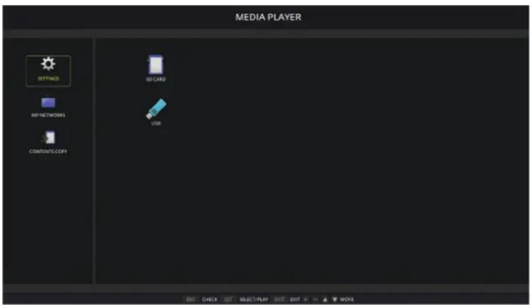
The following settings can be configured on the [SETTINGS] screen. Select [OK] then press SET button to save any changes; otherwise settings you selected are not saved.
Slideshow
| Menu Function | |
| SCREEN SIZE Selects [ACTUAL SIZE] or [BEST FIT]. | |
| PLAY MODE Selects [AUTO] or [MANUAL]. | |
| INTERVAL Sets interval time. | |
| REPEAT Check the check box to repeat slideshow. | |
| AUDIO FILE Selects an audio file. | |
| BGM Check the check box to enable BGM. | |
| PLAY END SCREEN | Selects a setting for when the slideshow finishes. |
| Black screen: When the slideshow finishes, a black screen is displayed. | |
| File list: When the slideshow finishes, it goes back to the file list screen. | |
| Save last screen: When the slideshow finishes, the last slideshow image is kept on the screen. | |
Auto Play
Automatically plays any pictures or videos in the selected folder when the monitor is turned on with MP as the selected input. The images and videos will be displayed in the "sorted" order.
| Menu Function | |
| AUTO PLAY OFF: | Automatic play mode is off. |
| SLIDESHOW: Automatically plays a selected file. | |
| FOLDER | The location on the USB storage device or microSD memory card where the files are located.Select [SD CARD] or [USB] then press ENT button to select the root directory of the SD CARD or USB device.If the files are in a sub-folder, highlight [SD CARD] or [USB] then press SET button, navigate to the folder that contains the files, and then press ENT button on the remote control. |
Preset Contents
When the monitor has no current signal input, the monitor automatically changes to the Media Player input and plays any picture or video files in the selected folder. For example, when a device such as Blu-ray player powers off, the monitor changes input from HDMI to MP and plays the files in the folder selected in this screen.
| Menu Function | |
| ENABLE Press [SET] to | check the box to enable Preset Contents. |
| FOLDER | The location on the USB storage device or microSD memory card where the files are located.Select [SD CARD] or [USB] then press ENT button to select the root directory of the SD CARD or USB device.If the files are in a sub-folder, highlight [SD CARD] or [USB] then press SET button, navigate to the folder that contains the files, and then press ENT button on the remote control. |
Network & Other Settings
The settings below are for configuring the network settings and shared folder settings for the Media Player only.
To configure the settings, navigate to the [NETWORK & OTHER SETTINGS] option and press the SET button on the remote control.
Network Settings for the Media Player
| Menu Function | |
| IP SETTING Network related settings to be configured for the Media Player. | |
| IP ADDRESS | Note that the IP address for the Media Player is different than the IP address for the monitor. If you want to manually assign an IP address for the monitor, you will need to assign one to the Media Player as well. Otherwise, the IP address will be automatically assigned to the Media Player and possible conflicts on the network may occur. |
| SUBNET MASK | |
| DEFAULT GATEWAY | |
| DNS | |
| DNS PRIMARY | |
| DNS SECONDARY | |
NETWORK INFORMATION shows the current network settings for the Media Player.
Shared Folder
The SHARED FOLDER options provide two different methods for copying files to the microSD memory card over a network. Please see "Copying Files to the microSD memory card" on page 62 for instructions using the SHARED FOLDER function after enabling and configuring them in this screen.
Shared SD Card Settings
Enable this option to allow computers or mobile devices to access the microSD memory card in the monitor via the Media Player's IP address. Files can be copied to, or deleted from, the microSD memory card using a web browser. See page 63.
| Menu Function | ||
| ENABLE Check the checkbox to enable [SHARED SD CARD SETTINGS]. | ||
| USER NAME The User Name for accessing the monitor. It is the monitor model name and cannot be changed. | ||
| PASSWORD Create | a password for accessing the microSD memory card. A password is not required. If no password is set, any user/person can access and copy files to the microSD memory card. | |
Select OK then press SET button on the remote control to save the settings. If OK is not pressed, the settings you configured are not saved.
Shared Folder Settings
This option allows you to access shared network folders, from within the Media Player, to copy files to the microSD memory card. Up to four folders can be added to the Shared Folder settings. See page 63.
After opening the [SHARED FOLDER SETTINGS], select one of the folders then press SET button to show the settings for configuring the network credentials.
| Menu Function | ||
| ENABLE Check the checkbox to enable the selected folder. | ||
| SHARED FOLDER | Set the IP address or name of the network shared folder location that contains the files for copying to the microSD memory card. | |
| USER NAME Input | the user name that has permission to access the shared network folder. | |
| PASSWORD Input | the password for the user name that is being used to access the shared folder. | |
Select OK then press SET button on the remote control to save the settings. If OK is not pressed, the settings you configured are not saved.
Shift to No Signal
Under normal operation on the other video input connections, when video signal is lost, such as when a Blu-ray player turns off, the monitor registers “No Signal” and enters power save mode.
When the Media Player is the current signal input, the Media Player is always on and sends video signal to the monitor. This prevents the monitor from entering power save mode, even when the Media Player is not actively playing files.
When SHIFT TO NO SIGNAL is enabled, the Media Player basically tells the monitor that there is no current video signal and to shift to no signal mode. This allows the monitor to register "No Signal" and enter power save mode, just as it would on the other video inputs when loss of video signal occurs.
The amount of time between when the Media Player is last used before it tells the monitor to shift to no signal can be adjusted.
The monitor shifts to no signal under the following conditions:
• After the Media Player stops playing content.
- While the monitor is displaying the Media Player home screen, USB ☐ window or SD CARD ☐ window, and no buttons have been pressed on the remote control or monitor control panel during the interval period you set.
| Menu Function | ||
| ENABLE Check the checkbox to enable [SHIFT TO NO SIGNAL]. | ||
| INTERVAL Set the time between when the Media Player is last used to when the monitor goes into no signal mode. | ||
Select OK then press SET button on the remote control to save the settings. If OK is not pressed, the settings you configured are not saved.
Copying Files to the microSD memory card
There are two options for copying files to the microSD memory card when it is already inserted in the monitor. Files can be copied from a network folder or a USB storage device via the CONTENTS COPY option, or via the SD-CARD VIEWER in a web browser.
Copying files from a USB storage device is useful to easily change the content on the microSD memory card, without removing the microSD memory card and its cover from the monitor. Copying the files from a network folder or via a web browser are useful when the monitor is in a location that is not easily accessible.
When using the CONTENTS COPY option, the microSD memory card will be erased then the files will be copied from the selected folder.
Copying Files to the microSD memory card
- Either connect a USB storage device to the Media Player USB port on the monitor, or configure the [SHARED FOLDER SETTINGS] in the Media Player's [NETWORK & OTHER SETTINGS] (see page 61).
- From the Media Player's home screen select [CONTENTS COPY] then press SET button.
The [CONTENTS COPY] screen shows any network folders that have been configured and the "USB" icon if a USB storage device is connected. - Select either USB or a network folder containing the files you want to copy to the microSD memory card then press SET button.
- On the confirmation screen, select OK then press SET button.
The entire contents of the network folder or USB storage device will be copied to the microSD memory card. Make sure the microSD memory card's storage capacity is large enough to save the files you want to add.
NOTE: “Out of disk space” is displayed if the microSD memory card storage capacity is not enough to copy the selected folder.
- When pressing OK to start CONTENTS COPY, previous data that was saved on the microSD memory card is immediately deleted. Canceling the CONTENTS COPY function will not restore the previous files.
• Devices that are not inserted will be displayed in gray.
- While the monitor is copying files, do not eject the microSD memory card from the monitor and do not turn off the monitor's main power. Ejecting the microSD memory card or turning off the monitor while copying files may corrupt the data.
- If you press the STANDBY button on the remote control or the ⏻ button on the monitor while the copy function is in progress, the image will disappear and the LED indicator will blink red. After the copy is complete, the LED indicator will light up red.
NOTE: If the connection to a shared folder fails, an error message is shown and an "x" is displayed on the folder icon. Check for the following if this occurs:
• Is the name of the network folder correct?
• Is the network folder set for sharing?
- Have access rights been set in the network folder?
- Are there displayable files saved in the network folder?
Using SD-CARD VIEWER in a Web Browser
When using the SD-CARD VIEWER to copy files to the microSD memory card, individual files can be added to the microSD memory card without first erasing its content. Because files are added to the microSD memory card via its web controls in an internet browser, files can be copied from either a computer or a mobile device, such as a tablet, that is connected to the same network as the monitor.
Copying Files to the microSD memory card
- Enable the [SHARED SD CARD] settings in the Media Player's [NETWORK & OTHER SETTINGS] (see page 61).
- Open a web browser on a computer or mobile device connected to the same network as the monitor.
- Input the IP address of the Media Player in the address field of the web browser, then press Enter to access the web controls.
The IP address for the Media Player is shown in the [NETWORK INFORMATION for MEDIA PLAYER] section of the [NETWORK & OTHER SETTINGS] screen. -
If a password has been created for accessing the card, input the user name and password.
The user name is the monitor's model name. Note that both the user name and password are case sensitive. -
When the computer or mobile device successfully connects to the Media Player, the Media Player's web controls are displayed in the browser. Select the SD-CARD VIEWER link on the left side of the browser window.

- Press the Choose File button to open a file browser, then select a file.
The file will be added to the root directory of the microSD memory card. To upload a file to a different folder on the microSD memory card, do one of the following:
- Upload to an existing folder – If you want to add the file to an existing folder on the microSD memory card, select the folder name to open the folder first, then press the Choose File button.
-
Upload to a new folder – If you want to create a new folder before uploading the file, press the CREATE button. Input a folder name in the NAME field and then press OK. The new folder appears in the microSD memory card file list. Select the new folder to open the folder, then press the Choose File button.
-
Navigate to the where the files you want to add to the card are located. Select the file you want to copy to the microSD memory card then press Open.
- Press OK to confirm the file upload.
- The file will now copy to the microSD memory card.
If you selected a file type that the Media Player cannot read, a message will show on the file upload screen that the file cannot be copied.
To delete files or folders from the microSD memory card, press the check boxes to select the items you want to delete then press the DELETE button.
NOTE: • While the monitor is copying files, do not eject the microSD memory card from the monitor and do not turn off the monitor's main power. Ejecting the microSD memory card or turning off the monitor while copying files may corrupt the data.
- If you press the STANDBY button on the remote control or the ⏻ button on the monitor while the LED indicator is blinking red, the monitor goes to standby state after completing the copy function.
- Only file formats for still images, motion video files, and BGM audio can be copied.
SD-CARD VIEWER Web Controls Buttons

1. CHOOSE FILE
Choose File opens a file browser to select a file to copy to the microSD memory card.
Pressing Open in the file browser shows the upload window displaying the selected file.
Pressing OK starts the file upload.
NOTE: Please check the microSD memory card storage capacity before copying files. STORAGE CAPACITY shows the connected microSD memory card capacity.
2. DELETE
Press the check boxes to select files and folders.
Pressing DELETE opens the DELETE FOLDERS/FILES window.
Pressing OK deletes the selected files or folders.
3. CREATE
Create opens a window to name and add a new folder to the microSD memory card.
Input folder name and select OK. A maximum of 255 alphanumeric characters is allowed.
4. RELOAD
Refreshes the microSD memory card data in the web browser.
5. THUMB/LIST
Switches between displaying the files using icons or thumbnails.
Displays a description of the file or folder if you select thumb name or file name.
6. SORT
Selects the sorting the method. The folders saved in the microSD memory card are sorted based on the selected sort method.
Connecting to a different monitor's SD-CARD VIEWER
If there is more than one monitor on the network that has a Media Player, you can search from any monitor's main web controls to display all supported monitors on the network.
- Input the monitor's IP address in the web browser's address field.
Press the DISPLAY button on the remote control to show the monitor's Information OSD on-screen, which displays the monitor's IP address.
The monitor and its Media Player have different IP addresses; both are automatically assigned by default when connected to a DHCP network.
- Select the [SD-CARD VIEWER] link on the left side of the browser window.
This displays a [GO TO SD-CARD VIEWER] window.
-
Press the SEARCH button to display the [IP ADDRESS] of the currently connected monitor and all compatible monitors on the same network.
-
Select the IP address, under the [IP ADDRESS (MP)] column, to access the Media Player's web controls for the monitor you want to copy files to.

To open the other monitor's web page in a new tab, right-click on its IP address. To open the other monitor's web page in a new window, left-click on its IP address.
Chapter 6 Multi-Monitor Setup
This Chapter Includes:
→ "Connecting Multiple Monitors" on page 68
→ "Video Out Connection" on page 70
→ "Setting the Remote Control ID Function" on page 71
Connecting Multiple Monitors
Monitors can be connected to each other, both communication and video connections, in multiple display installations. Chaining the video connections together creates a video wall where a single image can be tiled across all displays. When connecting multiple monitors to install a video wall, communication and video cable connections are necessary and their configuration must be carefully considered. Please refer to the "Wiring Diagram" on page 22 for making communication and video connections.
The monitor settings for configuring a video wall in the OSD and Monitor Webpage settings are under [MULTI-DISPLAY].
- [AUTO TILE MATRIX SETUP] – automatically configures the multi-display settings when the communication and video ports are chained together. This automatically sets the [MONITOR ID] and position of the monitors in the video wall following the physical wiring between the monitors.
Input the number of monitors arranged horizontally and vertically on the master monitor. The following settings are set automatically when you run the auto setup: [MONITOR ID], [TILE MATRIX], [TILE MATRIX MEM], [Input Signal], [DisplayPort] in [TERMINAL SETTINGS] and setting for video out.
NOTE: • [AUTO ID] will be automatically executed.
- When you use this function, it is recommended that monitors be chained by DisplayPort cable.
- This function is released if [MOTION] in [SCREEN SAVER] is activated.
Example of installation via LAN:
![graph TD A["Master monitor"] --> B["ID : 1"] B --> C["ID : 2"] C --> D["ID : 3"] D --> E["ID : 4"] E --> F["ID : 5"] F --> G["ID : 6"] G --> H["ID : 7"] H --> I["ID : 8"] I --> J["ID : 9"] J --> K["ID : 9"]](/content/2026/08/1616062/images/cd5b2cb98efba770c59492927c4ec2131d4f0e02972f027ecb324057cb5a5b1b.jpg)
![graph TD A["ID: 7"] --> B["7"] C["ID: 6"] --> D["4"] E["ID: 1"] --> F["1"] G["ID: 8"] --> H["8"] I["ID: 5"] --> J["5"] K["ID: 2"] --> L["2"] M["ID: 9"] --> N["9"] O["ID: 4"] --> P["6"] Q["ID: 3"] --> R["3"] S["Master monitor"] --> T["Top shaded region"]](/content/2026/08/1616062/images/bb996a6cbc2baf62ea4a2fafa71b001771f69b5a232192f7b53b57905773f1c8.jpg)
- [SETTING COPY] – copies some of the OSD menu categories to other monitors in the video wall, when chained together.
- [TILE MATRIX] – allows one image to be expanded and displayed over multiple screens (up to 100) through a distribution amplifier. Manually input the number of horizontal and vertical monitor in the video wall, position of the monitor in the wall, and turn on or off Tile Compensation. When tilting HDCP content, please refer to the "Video Out Connection" on page 70.
- [TILE COMP] - scales the displayed image to compensate for the width of the screen bezel in order to create a seamless image.
• [TILE CUT] - select a part of image from the displaying image. The selected part is displayed as a full image on the screen.
Example of TILE CUT 2x1 (Landscape)
For the left monitor:
- Set H MONITORS [2] and V MONITORS [2].
One image will be divided by 4 then put number from 1 to 4.
OSD Monitor screen


- Select 1 to 4 at [POSITION].
e.g. Selecting 1

- With [H ADJUSTMENT] and [V ADJUSTMENT], you can move the selected square to the exact spot where you display.

- Select [YES] at [TILE MATRIX ENABLE].

For the right monitor:
Repeat the same steps.
e.g. Selecting 2 at [POSITION]

After individually setting, the 2x1 image (Landscape) will be shown as below.

- [FRAME COMP] - Allows auto setting of FRAME COMP by inputting the number of monitors arranged horizontally and vertically on. It is recommended and should deliver the best results if fast moving content is displayed. Applying the [FRAME COMP] is needed for a specific installation.
[AUTO] - Sets total delay value, each delay value is set automatically by setting of [H MONITORS], [V MONITORS] and [POSITION] in TILE MATRIX.
[MANUAL] - Sets delay value to every monitors.
• [V SCAN REVERSE] - Reverse scanning image direction to create a smooth motion image.
ORIGINAL FRAME COMP V SCAN REVERSE

- [TILE MATRIX MEMORY] – allows settings for the tile matrix to be saved to all inputs in the monitor.
- [ID CONTROL] – sets the monitor ID and group IP for the current monitor. When the monitors LAN ports are chained together, the ID and IP can be automatically assigned to all displays.
• Video daisy chaining.
Please use the same monitor model for all monitors in the connected daisy-chain.
MONITORS POSITION is different from ID. Please refer to the figure1 and figure 2.

Figure 2
Video Out Connection
| Main picture | DisplayPort1 | DisplayPort2 | DVI | HDMI1 | HDMI2 | VGA (RGB) | VGA (YPbPr) | Video OPTION MP | |||
| Connector | DisplayPort1 (DAISY CHAIN IN) | DisplayPort2 | DVI-D | HDMI1 (DAISY CHAIN IN) | HDMI2 (CEC) | VGA (RGB, YPbPr) | Option Board Slot (SLOT2 (DP)) | Option Board Slot (SLOT2 (HDMI)) | - | ||
| DisplayPort HDMI | Yes | No | No | No | No | No | No | No | Yes | No | No |
| No | No | Yes | Yes | No | No | No | No | No | Yes | Yes | |
NOTE: The output of Media Player signal (MP) is capable only between the same models.
For connecting multiple monitors with HDMI cable
• Using the same display model.
- Set the same ([MODE1] or [MODE2]) at [HDMI] in [TERMINAL SETTINGS] in all connected multiple monitors.
For DisplayPort Out
- Select either the DisplayPort1 or OPTION input for the monitor to output a signal from DisplayPort Out.
- This monitor's signal output function supports contents protected by HDCP. HDCP content can be distributed across up to 3 connected monitors.
- When using an Option Board, please set [SLOT2 CH SETTING] to [CH1] then set [SLOT2 CH SELECT] to DisplayPort. See page 118.
NOTE: Please use slot2 type option boards which outputs DisplayPort signal.
For HDMI Out
- Select either the HDMI1, DVI, MP, or OPTION input for the monitor to output a signal from HDMI OUT.
- This monitor's signal output function supports contents protected by HDCP.
HDCP content can be distributed across multiple connected monitors as described below:
• HDCP 1: Up to 8 monitors / HDCP 2.2: Up to 5 monitors.
- The time until image is displayed depends on the number of connected monitors.
• Without HDCP: Up to 9 monitors.
NOTE: • Depending on the device you use, number of monitor connection will change.
- When displaying an image in a multi-monitor setting, do not disconnect cables from the monitors. When you disconnect cables, please turn the main power off first.
- When using an option, please set [SLOT2 CH SETTING] to [CH1] then set [SLOT2 CH SELECT] to TMDS. See page 118.
NOTE: Please use slot2 type option boards which outputs HDMI signal.
For HDCP Content
HDCP is a system for preventing illegal copying of video data sent over a digital signal. If you are unable to view material via the digital inputs, this does not necessarily mean that the monitor is not functioning properly. With the implementation of HDCP, there may be cases in which certain content is protected by HDCP and might not be displayed due to the decision/intention of the HDCP community (Digital Content Protection, LLC).
Due to these security restrictions in video content, HDCP video content can only be tiled across a limited number of monitors. HDCP video content is generally commercially produced Blu-rays and DVDs, television broadcast, and streaming media services.
Setting the Remote Control ID Function
The optional remote control can be used to control up to 100 individual monitors using what is called the REMOTE CONTROL ID mode. The REMOTE CONTROL ID mode works in conjunction with the Monitor ID, allowing control of up to 100 individual monitors. For example, if there are many monitors being used in the same area, a remote control in normal mode would send signals to every monitor at the same time (see Figure 1). Using the remote in REMOTE CONTROL ID mode will only operate one specific monitor within the group (see Figure 2).
To Set Remote Control ID (Entering REMOTE CONTROL ID mode)
While holding down the REMOTE ID SET button on the remote control, use the KEYPAD to input the Monitor ID (1-100) of the monitor to be controlled via remote. The remote control can then be used to operate the monitor having that specific Monitor ID number.
When 0 is selected or when the remote control is in normal mode, all monitors will be operated.
To Reset Remote Control Mode
Normal Mode - To return to Normal Mode press the REMOTE ID CLEAR button and hold down for 5 seconds.
NOTE: In order for this feature to work properly, the monitor must be assigned a Monitor ID number. The Monitor ID number can be assigned under the MULTI DISPLAY menu in the OSD. See page 111.
- Point the remote control towards the remote sensor of the desired monitor and press the REMOTE ID SET button. The MONITOR ID number is shown on the screen when your remote control is in ID mode.
Use the Remote to Control all Monitors in Range
-
On the remote control, press and hold down the REMOTE ID SET button while using the keypad to input the REMOTE CONTROL ID number "0".
-
All monitors within range of the remote control will now respond to keypad press.
NOTE: When the REMOTE ID is set to "0", pressing REMOTE ID SET will make all monitors, within range of the remote signal, display their Monitor ID on screen. This way you can easily see what the monitor ID is if you want to control a single monitor, as described below.
![graph TD A["Monitor ID:1 Monitor ID:2 Monitor ID:3"] --> B["Remote works Remote works Remote works"] B --> C["Figure 1 Remote in Normal mode or the REMOTE ID is set to 0"] C --> D["Remote works Remote works Remote works"] D --> E["Figure 2 Remote set up to use REMOTE ID:3"] E --> F["Remote does not…](/content/2026/08/1616062/images/38621964708ebf52a33848df435fc678350c5acc19d38e12ab9cca4baf833548.jpg)
Use the remote control to operate a monitor that has a specific MONITOR ID number assigned to it.
- Set the [MONITOR ID] number for the monitor (see page 111). The [MONITOR ID] number can range from 1-100.
This [MONITOR ID] number allows the remote control to operate this specific monitor without affecting other monitors.
- On the remote control, press and hold down the REMOTE ID SET button while using the keypad to input the REMOTE CONTROL ID number (1-100). The REMOTE ID NUMBER should match the MONITOR ID number of the monitor to be controlled.
- Point the remote control towards the remote sensor of the desired monitor and press the REMOTE ID SET button.
The MONITOR ID number is shown in red on the monitor.
If the REMOTE CONTROL ID is "0", then all monitors in range will show their respective MONITOR ID number in red.
If the MONITOR ID number is shown in white on the monitor, the MONITOR ID number and the REMOTE CONTROL ID are not the same.
Chapter 7 External Control
This Chapter Includes:
→ "Connecting Interfaces" on page 74
→ "Controlling the Monitor via RS-232C" on page 77
→ "Controlling the Monitor via LAN" on page 78
→ "Proof of Play" on page 86
Connecting external device
There are two options to connect an external device to control the monitor.
Display Wall Calibrator or NaViSet Administrator allows you to control the monitor settings and get the monitor status, including calibration information.
- RS-232C terminal.
Connecting an external device to the RS-232C terminal of the monitor with a RS-232C cable.
• LAN port.
Connecting a network to the LAN1 (DAISY CHAIN IN) port of the monitor with a LAN cable (RJ45 category 3 or higher).
Network
- When you use a network, your communication data is exposed to the risks of being stolen or illegally accessed. To avoid these risks, you need to use this monitor in a secure network environment.
Connecting Interfaces
RS-232C Interface
| PROTOCOL RS-232C | |
| BAUD RATE 9600 [bps] | |
| DATA LENGTH 8 [bits] | |
| PARITY NONE | |
| STOP BIT 1 [bit] | |
| FLOW CONTROL NONE | |
LAN Interface
| PROTOCOL TCP | |
| PORT NUMBER 7142 | |
| COMMUNICATION SPEED AUTO setting (10/100Mbps) | |
Commands
Control command
The display supports two basic types of command formats:
• Binary communications: A sequence of encoded bytes that includes support for controlling almost all monitor functions.
- ASCII Control commands: This uses simple "English-like syntax" control commands using ASCII, for performing many common functions easily.
NOTE: The command formats for both types is explained in the external documents "External Control" PDF document. See page 95.
The table below gives some examples of the binary commands for several common functions. The data is listed as hexadecimal bytes. These examples assume the Monitor ID is 1.
| Function (Monitor ID = 1) Code Data | |
| Power ON | 01 30 41 30 41 30 43 02 43 32 30 33 44 36 30 30 30 31 03 73 0d |
| Power OFF | 01 30 41 30 41 30 43 02 43 32 30 33 44 36 30 30 30 34 03 76 0d |
| Input Source Select DisplayPort1 | 01 30 41 30 45 30 41 02 30 30 36 30 30 30 46 03 04 0dor01 30 41 30 45 30 41 02 31 31 30 36 30 30 30 46 03 04 0d |
| Input Source Select DisplayPort2 | 01 30 41 30 45 30 41 02 30 30 36 30 30 30 31 30 03 73 0dor01 30 41 30 45 30 41 02 31 31 30 36 30 30 31 30 03 73 0d |
| Input Source Select DVI | 01 30 41 30 45 30 41 02 30 30 36 30 30 30 30 33 03 71 0dor01 30 41 30 45 30 41 02 31 31 30 36 30 30 30 33 03 71 0d |
| Input Source Select HDMI1 | 01 30 41 30 45 30 41 02 30 30 36 30 30 30 31 31 03 72 0dor01 30 41 30 45 30 41 02 31 31 30 36 30 30 31 31 03 72 0d |
| Input Source Select HDMI2 | 01 30 41 30 45 30 41 02 30 30 36 30 30 30 31 32 03 71 0dor01 30 41 30 45 30 41 02 31 31 30 36 30 30 31 32 03 71 0d |
| Input Source Select VGA (RGB) 01 30 41 30 | 45 30 41 02 30 30 36 30 30 30 31 03 73 0d |
| Input Source Select VGA (YPbPr) | 01 30 41 30 45 30 41 02 30 30 36 30 30 30 43 03 01 0d |
| Input Source Select VIDEO | 01 30 41 30 45 30 41 02 30 30 36 30 30 30 35 03 77 0d |
| Input Source Select MP 01 30 41 30 45 30 41 | 02 30 30 36 30 30 30 38 37 03 7D 0dor01 30 41 30 45 30 41 02 31 31 30 36 30 30 38 37 03 7D 0d |
| Input Source Select OPTION 01 30 41 30 45 | 30 41 02 30 30 36 30 30 30 30 44 03 06 0dor01 30 41 30 45 30 41 02 31 31 30 36 30 30 30 44 03 06 0d |
| Sound Mute ON 01 30 41 30 45 30 41 02 30 | 30 38 44 30 30 30 31 03 09 0d |
| Sound Mute OFF 01 30 41 30 45 30 41 02 30 | 30 38 44 30 30 30 32 03 0a 0d |
ASCII Control command
This monitor supports control command, which is listed in the "External Control" PDF document (See page 95), but also supports common ASCII control command, which is used for controlling the SHARP monitor or projector from a connected PC. For further information please visit our website.
Parameter
Input command Status command
| Input signal name Response Parameter Response Error status | ||
| DVI dvi dvi or dvi1 error:temp Temperature abnormal | ||
| HDMI1 | hdmi1 | hdmi1 or hdmi |
| HDMI2 | hdmi2 | hdmi2 |
| DisplayPort1 | DisplayPort1 | DisplayPort1 or DisplayPort |
| DisplayPort2 | DisplayPort2 | DisplayPort2 |
| VGA | vga | vga, vga1, computer,computer1, rgb or rgb1 |
| VIDEO | video | video or video1 |
| MP | mp | mp |
| OPTION | option | option |
| error:fan | Cooling fan abnormal |
| error:light | Inverter or backlight abnormal |
| error:system | System error |
Please connect a CEC supporting device to HDMI2 port.
| OSD menu HDMI CEC command name Explanation Setting | |||
| CEC(Consumer Electronics Control) | One Touch Play When a CEC supported HDMI device is turned on, the monitor connected to the device by an HDMI cable also automatically turns on. After the monitor powers on, [INPUT] automatically switches to the [HDMI2].If the monitor is turned on when HDMI CEC devices are turned on, it changes the [INPUT] from the current one to [HDMI2]. |  To set the CEC options, please follow the steps below.Press the Menu button to open the OSD.Using the ▲▼ buttons, navigate to [CONTROL] to [CEC], then press SET button to enter the CEC options.Use the ▶◀ buttons to highlight [MODE], then press SET button to enable CEC. To set the CEC options, please follow the steps below.Press the Menu button to open the OSD.Using the ▲▼ buttons, navigate to [CONTROL] to [CEC], then press SET button to enter the CEC options.Use the ▶◀ buttons to highlight [MODE], then press SET button to enable CEC. | |
| Remote Control Pass Through The monitor's optional wireless remote control button operation can function with HDMI CEC supporting devices.For example, if turning on the monitor by wireless remote control and pressing the play button, a HDMI CEC supporting device can also be turned on and play. | |||
| Power Status Connected HDMI CEC supporting devicesobtain the monitor's power status, such as if the monitor is in standby state or on. | |||
| System Information This function obtains the information for a connected HDMI CEC supported device (CEC version, Physical Address). In addition, this function copes with the "Change Language function".If the language for the monitor is changed, the language for a connected HDMI CEC supported device is changed to the same language, which is selected for the monitor.For the "Change Language function", it is necessary that the connected HDMI CEC supported device be able to cope with multi-language. | |||
| AUTOTURN OFF | System Standby | If the monitor is set to standby state using the optional wireless remote control, HDMI CEC supported devices also go into standby state at the same time.If the monitor goes into standby state while an HDMI CEC supported device is recording, the device remains on. Please refer to the user's manual supplied with the HDMI CEC supported device for further information. | Use the ▲▼ buttons to select [AUTO TURN OFF].Use the ▶◀ buttons to highlight [YES], then press the SET button to select [YES]. |
| AUDIO RECEIVER | System Audio Control | Please set an HDMI CEC audio amplifier between the monitor and an HDMI CEC supported device with an HDMI cable.The Volume button on the optional wireless remote control can control the volume of the connected HDMI CEC audio amplifier.While this function is active, the external speaker connected to the monitor is set to MUTE automatically. | Use the ▲▼ buttons to select [AUDIO RECEIVER] then press SET.Use the ▶◀ buttons to highlight [YES], then press the SET button to select [YES]. |
| SEARCH DEVICE | Device OSD Name Transfer | Use the ▶◀ buttons to highlight YES, then press the SET button to start the search. | Use the ▲▼ buttons to select [SEARCH DEVICE].This function searches for CEC supported devices on the monitor's HDMI connections. If a CEC device is successfully detected, this function obtains the device's name. The device's name and the HDMI connection it is found on are displayed. |
| Routing Control | By selecting a device name, the HDMI CEC supported device input switches to the input you selected. After selecting the device, wireless remote control operation functions for the selected device. | ||
| This CEC function is supporting Feature Abort.Please refer to Connections (see page 21) for HDMI CEC devices connection. | |||
Controlling the Monitor via RS-232C
This monitor can be controlled by connecting a personal computer with an RS-232C (reverse type) terminal.
For example, some of the functions that can be controlled by a personal computer are:
• Power ON or standby state.
- Switching between input signals.
• Sound Mute ON or OFF.
Connection
Monitor + computer.
- Please turn off the monitor's main power before connecting a computer to the monitor.
- Please turn on the connected computer first then turn on the monitor's main power.
If you turn on the computer and monitor in reverse order, the com port may not work.
![graph TD A["Computer"] --> B["RS-232C Cable"] B --> C["RS-232C"] C --> D["Computer"]](/content/2026/08/1616062/images/6b718927042400e92e6f98434c10f2a155f7f5488b1c4c5c6cbf08ce43804a99.jpg)
NOTE: • If your computer is equipped only with a 25-pin serial port connector, a 25-pin serial port adapter is required. Contact your supplier for details.
- For the pin assignment, please see "RS-232C input/output" on page 78.
To control the monitor via commands sent from a computer connected with an RS-232C cable, please use the control command. Instructions for the control command can be found in the Control Command Diagram (see page 74) or the "External Control" PDF document. See page 95.
Interface
| PROTOCOL RS-232C | |
| BAUD RATE 9600 [bps] | |
| DATA LENGTH 8 [bits] | |
| PARITY NONE | |
| STOP BIT 1 [bit] | |
| FLOW CONTROL NONE | |
This monitor uses RXD, TXD and GND lines for RS-232C control.
The reverse type cable (null modem cable) (not included) should be used for RS-232C control.
PIN ASSIGNMENT
RS-232C input/output
| Pin No Name | |
| 1 | NC |
| 2 RXD | |
| 3 TXD | |
| 4 | NC |
| 5 GND | |
| 6 | NC |
| 7 | NC |
| 8 | NC |
| 9 | NC |

This monitor uses RXD, TXD and GND lines for RS-232C control.
Controlling the Monitor via LAN
Connecting to a Network
Using a LAN cable allows you to specify the Network Settings and the Alert Mail Settings by using an HTTP server function. To use a LAN connection, you are required to assign an IP address. The monitor will obtain an IP address automatically when connected to a DHCP network.
Example of LAN connection:
![graph TD Server["Server"] --> Hub["Hub"] Hub --> LAN1["LAN1 (DAISY CHAIN IN)"] Hub --> LAN2["LAN2 (DAISY CHAIN OUT)"] LAN1 --> LAN2 LAN2 --> LAN1 Note["NOTE: Use a category 5 or higher LAN cable."]](/content/2026/08/1616062/images/12c788756c28a57509bd3ca9502553794856a452bdf8fd9dac6f337e35cc1afc.jpg)
Multiple Monitors Connection
You can control multiple monitors by using RS-232C, REMOTE or LAN daisy-chain connection.
NOTE: • Up to 100 monitors can be daisy chained together. Please execute AUTO ID/IP to automatically assign unique IDs to each monitor (see page 111) before trying to control a monitor by manually specifying the ID number.
| Master Monitor Sub Monitors | |||
| Connector Connector | |||
| IN OUT IN OUT | |||
| RS-232C | LAN2 (DAISY CHAIN OUT) | LAN1 (DAISY CHAIN IN) | LAN2 (DAISY CHAIN OUT) |
| REMOTE | |||
| LAN1 (DAISY CHAIN IN) | |||
Connection
![graph LR A["Device 1"] --> B["LAN2"] B --> C["LAN Cable"] C --> D["LAN1"] D --> E["LAN2"] E --> F["LAN1"] F --> G["LAN2"] G --> H["Next monitor"]](/content/2026/08/1616062/images/52c2038101c9c4a8a9df169d42545f926a22a50dd4555a09abf2d6ac7f1374f8.jpg)
Overview
Connecting the monitor to a network allows for remote control of the monitor from a computer connected to the same network.
The IP address and subnet mask of the monitor can be set on the Network Setting screen of the web browser by using an HTTP server. When connecting to a DHCP server, the IP address and subnet mask will be obtained automatically when the monitor is turned on. Please be sure to use "Microsoft Internet Explorer 10" or a higher version for the web browser.
This device uses “JavaScript” and “Cookies” and the browser should be set to accept these functions. Refer to the help files for the web browser to change the settings to use JavaScript and Cookies.
To access the HTTP server, launch a web browser on a computer connected to the same network as the monitor and enter the following URL in the web address field:
Network Setting
http://
NOTE: • The default IP address is assigned automatically to the monitor.
- NaViSet Administrator software for managing monitors over the network is recommended. It can be download from the SHARP Display website (See page 95).
- If the [MONITOR NETWORK SETTINGS] screen does not appear in the web browser, press the Ctrl+F5 keys to refresh your web browser (or clear the cache).
- If the monitor appears to be slow in response to commands or clicks on buttons in the browser, or the general speed of operation is unacceptable, this may be due to network traffic or the settings on your network. Should this happen, consult your network administrator.
- The monitor may not respond if the buttons shown on the browser are repeatedly pressed in rapid intervals. Should this happen, wait a moment and repeat. If you still can't get a response, turn the monitor off and then back on.
Preparation Before Use
Connect the monitor to the network, using a commercially available LAN cable, before attempting to use browser operations.
Operation with a browser that uses a proxy server may not be possible depending on the type of proxy server and the setting method. Although the type of proxy server will be a factor, it is possible that items that have been set will not be shown, depending on the effectiveness of the cache, and the contents set from the browser may not be reflected in operation. It is recommended that a proxy server is not used unless the network environment requires it.
Handling of the Address for Operation via a Browser
A host name can be used in the following cases (corresponding to the IP address of the monitor):
The host name must be registered in the domain name system (DNS) by the network administrator. You can then access the network settings of the monitor via this registered host name by using a compatible browser.
If the host name has been configured in the "HOSTS" file of the computer being used, you can then access the network settings of the monitor via this host name by using a compatible browser.
Operation
Access the following address to show HOME.
http://
Click each link on the left column below HOME.
REMOTE CONTROL
Enable an operation to control the monitor equivalent to the keys on the remote control.
OSD Menu Settings in the Monitor Web controls
Select one of the links on the left side of the monitor web controls to configure the settings available in the monitor's OSD. Please see page 97 for the full list of OSD menu controls.
[INPUT], [PICTURE], [AUDIO], [SCHEDULE], [MULTI INPUT], [OSD], [MULTI DISPLAY], [DISPLAY PROTECTION], [CONTROL], [OPTION], [SYSTEM]

NOTE: The buttons in the monitor web controls function as follows:
[APPLY]: Saves the settings.
[CANCEL]: Returns to the previous settings.
NOTE: CANCEL is disabled after clicking APPLY.
[RELOAD]: Reloads the settings.
[RESET]: Resets to the initial settings.
Click on "NETWORK" on the left column below HOME.

| IP SETTING Select an | option for setting the IP ADDRESS.AUTO: Automatically assign an IP address.MANUAL: Manually set an IP address for the monitor connected to the network.NOTE: Consult your network administrator if you have any trouble. |
| IP ADDRESS | Set your IP address for the monitor connected to the network when [MANUAL] is selected for [IP SETTING]. |
| SUBNET MASK Set your subnet mask data for the monitor connected to the network when [MANUAL] is selected for [IP SETTING]. | |
| DEFAULT GATEWAY | Set your default gateway for the monitor connected to the network when [MANUAL] is selected for [IP SETTING].NOTE: Set as [0.0.0.0] to delete the setting. |
| DNS Set for IP ADDRESS | ESS setting of DNS server.AUTO: The DNS server connected to the monitor will automatically assign its IP address.MANUAL: Manually enter the IP address of the DNS server that is connected with the monitor. |
| PRIMARY DNS Enter | the primary DNS server settings of the network connected with the monitor.NOTE: Enter [0.0.0.0] to delete the setting. |
| SECONDARY DNS Enter | the secondary DNS server settings of the network connected with the monitor.NOTE: Enter [0.0.0.0] to delete the setting. |
NOTE: The following settings will be set back to the factory settings when IP ADDRESS RESET is selected at CONTROL of the OSD:
[IP SETTING]: AUTO, [IP ADDRESS]: 192.168.0.10, [SUBNET MASK]: 255.255.255.0, [DNS]: AUTO [DEFAULT GATEWAY], [PRIMARY DNS] and [SECONDARY DNS] are blank.
Mail Setting
Click on "MAIL" on the left column below HOME.
When the Mail settings are configured and enabled, the monitor sends email notifications when an error occurs or if the input signal is lost. The monitor must be connected to a LAN for this feature to work.
| Alert Mail When an error occurs, the monitor will send an error message to the email address(es) listed in the Recipient's Address fields. Please see the “Alert error message list” table below.Note that it is not an error when no input signal is detected. The monitor will only send a no signal input notification email when Status Message is enabled.Selecting [ENABLE] turns on the Alert Mail feature.Selecting [DISABLE] turns off the Alert Mail feature. | |
| Status Message This is a setting whether to include no signal condition as a alerting condition or not.Selecting [ENABLE], Alert Mail send mails when the monitor is no signal or in alerting conditions.Selecting [DISABLE], Alert Mail send mails when the monitor is in alerting conditions.It doesn't send mail when the monitor is no signal. | |
| Sender's Address Type in the sender's address. Up to 60 alphanumeric and symbols characters can be used. | |
| SMTP Server Type in the SMTP server name to be connected with the monitor.Up to 60 alphanumeric characters can be used. | |
| Recipient's Address Type in your recipient's address. Up to 60 alphanumeric and symbols characters can be used.1 to 3 | |
| Authentication Method This selects the authentication method of the email transmission. | |
| POP3 Server | This specifies the address of the POP3 server that is used in the authentication of the email. |
| User Name This sets the user name for logging into the authentication server when authentication is requiredfor the email transmission. Up to 60 alphanumeric characters can be used. | |
| Password This sets the password for logging into the authentication server when authentication is requiredfor the email transmission. Up to 60 alphanumeric characters can be used. | |
| Test Mail Click on this button to send a test email to check if your settings are correct. | |
NOTE: • If an alert email isn't received when performing a Test Mail, check that the network and server settings, and the recipient's email address are correct.
- If you entered an incorrect address in a test, you may not receive an Alert email. Should this happen, check that the Recipient's Address is correct.
Alert error message list
| Error number * ErrorCode | Alert mail Message | Explanation | Measure |
| 70h ~ 7Fh | The monitor's power supply is not functioning normally. | Standby power abnormal | Please contact your supplier. |
| 80h ~ Fh | The cooling fan has stopped. | Cooling fan abnormal | Please contact your supplier. |
| 90h ~ 9Fh | The monitor's backlight unit is not functioning normally. | Backlight abnormal | Please contact your supplier. |
| A0h ~ AFh | The monitor is overheated. | Temperature abnormal | Please contact your supplier. |
| A2h | A Sensor reached the temperature limit which was specified in the OSD.*Condition: DISPLAY PROTECTION-FAN CONTROL-COOLING FAN = AUTO | Reconfirm the settings in the [FAN CONTROL] in the [DISPLAY PROTECTION]. Or please contact your supplier. | |
| B0h ~ BFh | The monitor does not receive an input signal. | No signal | Please check “No picture” in “Troubleshooting”. |
| D0h | The remaining capacity of the error log decreased. | The Proof of Play log memory size is 1 more hour. | Please get a log by using PD external command. See page 86. |
| D1h | The battery for clocks is empty. | The battery is empty. | Please connect the monitor to the power then recharge the battery. Please set (DATE & TIME) in OSD. |
| E0h ~ EFh | A system error occurred in the monitor. | System error. | Please contact your supplier. |
SNMP Settings
Click on "SNMP" on the left column below HOME.
The SNMP protocol is used to get status information and to control a monitor directly via the network.
Version:
SNMP v1 Authenticated plaintext by community name, does not return a confirmation message of the trap.
SNMP v2c Authenticated plaintext by community name, returns a confirmation message of the trap.
Community name:
The default setting of community name is "public". It is read only. You can set community names for up to 3 settings.
Trap:
Sending error message to a specified address when an error occurs in the monitor.
| Check Box Explanation Error code | ||
| Temperature Temperature abnormal 0xA0, 0xA1, 0xA2 | ||
| Fan Cooling fan abnormal 0x80, 0x81 | ||
| Power Power abnormal 0x70, 0x71, 0x72, 0x78 | ||
| Inverter/Backlight Inverter or backlight abnormal 0x90, 0x91 | ||
| No Signal | No signal 0xB0 | |
| PROOF OF PLAY | Lower the log storage | 0xD0 |
| System Error | System error | 0xE0 |
AMX Settings
Click on "AMX" on the left column below HOME.
| AMX BEACON | To turn on or off for the detection from AMX Device Discovery when connecting to a network supported by an AMX’s NetLinx control system.HINT:When using a device that supports AMX Device Discovery, all AMX NetLinx control systems will recognize the device and download the appropriate Device Discovery Module from an AMX server.Selecting [ENABLE] AMX Device Discovery will detect the device.Selecting [DISABLE] AMX Device Discovery will not detect the device. |
Name Settings
Click on "NAME" on the left column below HOME.
| MONITOR NAME | Allows you to customize the monitor's name, up to a maximum of 16 characters long. This name is displayed when searching for devices on the network when using an application such as NaViSet Administrator. Giving the monitor a unique name allows it to be easily identified when viewing a list of monitors on the network. The default name is the monitor's model name. |
| Host Name(CONTROL) | Type in the hostname of the monitor which is connected to the network.Up to 15 alphanumeric characters can be used. |
| HOST NAME (MP) | Type in the hostname of the network to be used in the Media Player connected to the monitor.Up to 15 alphanumeric characters can be used. |
| Domain Name | Type in the domain name of the network which is connected with the monitor.Up to 60 alphanumeric characters can be used. |
Network Service Settings
Click on "NETWORK SERVICE" on the left column below HOME.
| PJLink CLASS Set a class for PJLink*.NOTE: PJLink is a network interface standard that JBMIA established.http://pjlink.jbmia.or.jp/index.htmlThis monitor is available for class1 and class2 command. | |
| NOTIFY FUNCTION ENABLE | Enable or disable a notification of the monitor network condition. This function is only for class2. |
| NOTIFY ADDRESS | Set an IP ADDRESS to which the monitor network status will be sent. This function is only for class2. |
| PJLink PASSWORD Set a password for PJLink*. The password must be max. 32 characters long. Do not forget your password. If you forget your password, consult your supplier. | |
| HTTP PASSWORD Set a password for the HTTP server. The password must be max. 10 characters long. | |
| HTTP PASSWORD ENABLE | An HTTP PASSWORD is required when logging into the HTTP server. |
*What is PJLink?
PJLink is a standardization of protocol used for controlling devices of different manufacturers. This standard protocol was established by Japan Business Machine and Information System Industries Association (JBMIA) in 2005.
The device supports all commands of PJLink.
PD LIST Information
Click on "PD LIST" on the left column below HOME.
Shows a list of monitor IDs and IP addresses of multiple monitors which are daisy-chained.
NOTE: Only the master monitor can show the list.
MEMO Settings
Click on "MEMO" on the left column below HOME.
Use the MEMO settings to define text that can be viewed on-screen when a user selects MEMO in the OSD menu. For example, if you want to provide contact information for customer service at your company, that information can be entered here.
Note that the MEMO text cannot be set from the monitor's OSD menu using the remote control. The MEMO text must be added in the fields in this section. The message is displayed on the monitor screen.
| TITLE The title must be max. 24 characters long. | |
| MESSAGE A message must be max. 240 characters long. | |
| MEMO PASSWORD The default is “0000”. | |
| MEMO PASSWORD ENABLE | A MEMO PASSWORD is required when selecting MEMO PASSWORD ENABLE. |
SD-CARD VIEWER setting
Click "SD-CARD VIEWER" on the left side of HOME.
Please refer to Using SHARED SD card SETTINGS. See page 61.
Proof of Play
This function allows sending of messages for the current status of the monitor by self-diagnosis.
For the Proof of Play function including self-diagnosis, please see the "External Control" PDF document. See page 95.
| Check item Message | ||
| 1 | INPUT DVI, DisplayPort1, DisplayPort2, HDMI1, HDMI2, OPTION*, MP, VGA (RGB/YPbPr), VIDEO | |
| 2 | Resolution e.g. (H)1920, (V)1080, (H)1360, (V)768 or No signal or Invalid signal | |
| 3 | AUDIO INPUT IN1, IN2, DisplayPort1, DisplayPort2, HDMI1, HDMI2, OPTION*, MP | |
| 4 | Audio signal Audio in or No Audio in or N/A (IN1, IN2, OPTION (analog)*) | |
| 5 | Picture Image Normal Picture or No Picture | |
| 6 | AUDIO OUT Normal Audio or No Audio | |
| 7 | TIME (year)/(month)/(day)/(hour)/(minutes)/(second) | |
| 8 | EXPANSION DATA | 00h: Normal Proof of Play event01h: Proof of Play event is “last power on time”10h: MEDIA PLAYER is stop11h: MEDIA PLAYER is start12h: MEDIA PLAYER is pause13h: MEDIA PLAYER error occur20h: Contents Copy from USB21h: Contents Copy form network folder30h: Contents Copy Success31h: Contents Copy Error (No media)32h: Contents Copy Error (Connect error)33h: Contents Copy Error (Out of disk space)34h: Contents Copy Error (Read/Write error)40h: Human detected (Human sensor Status)41h: Human detect cleared (Human Sensor Status) |
*: This function depends on which Option Board installed in the monitor.
Example:
① HDMI1
② 1920 x 1080
③ HDMI1
④ IN1
⑤ Normal Picture
⑥ Normal Audio
⑦ 2014/1/1/0h/0m/0s
⑧ 10h: MEDIA PLAYER is stop
Chapter 8 Troubleshooting
This Chapter Includes:
→ "Screen Image and Video Signal Issues" on page 88
→ "Hardware Issues" on page 89
→ "Image Persistence" on page 91
No picture
- The signal cable should be completely connected to the display card/computer.
- The display card should be completely seated in its slot.
- Check the main Power Switch, it should be in the ON position.
- Make sure both the computer and monitor are powered on.
- Make sure that a supported resolution has been selected on the display card or system being used. If in doubt, please refer to the user's manual of the display controller or system to change the resolution.
- Check the monitor and your display card with respect to compatibility and recommended signal timings.
- Check the signal cable connector for bent or pushed-in pins.
- The monitor automatically goes into standby state at the preset time period after the video signal is lost. Press the power on button on the remote control or press the ⏻ button on the monitor.
- Check the [DVI MODE] settings when a DVD player or computer equipment is connected to the DVI input.
- If you unplug the signal cable when starting the computer, images may not be displayed. Turn off the monitor and the computer and then connect the signal cable and turn on the computer and the monitor.
- Check the [OPTION POWER] setting when you use Option Board accessories.
- Check for HDCP (High-bandwidth Digital Content Protection) content. HDCP is a system for preventing illegal copying of video data sent over a digital signal. If you are unable to view material via the digital inputs, this does not necessarily mean that the monitor is not functioning properly. With the implementation of HDCP, there may be cases in which certain content is protected by HDCP and might not be displayed due to the decision/intention of the HDCP community (Digital Content Protection, LLC).
Snowy Picture, Black Screen in DVI input
- Check the DVI MODE setting when a DVD player or computer equipment is connected to the DVI input.
Image persistence
- Please be aware that LCD Technology may experience a phenomenon known as Image Persistence. Image Persistence occurs when a residual or “ghost” image of a previous image remains visible on the screen. Unlike CRT monitors, the image persistence of monitors is not permanent, but single still image being displayed for a long period of time should be avoided. To alleviate image persistence, put the monitor into standby state via remote control or turn the monitor’s main power off for as long as the previous image was displayed. For example, if an image was on the monitor for one hour and a residual image remains, the monitor should be in standby state or main power off for one hour to erase the image.
NOTE: As with all personal display devices, we recommend showing moving images, or changing still images at regular intervals whenever the screen is idle, or putting the monitor into standby or turning it off when not in use.
The image is blinking
- If you use a signal repeater or distributor or a long cable, this may cause image roughness or blink for a moment. In this case please connect the cable to the monitor directly without using a repeater or a distributor, or replace the cable with a higher quality cable. Using a twisted pair extender may cause image roughness depending on the environment where the monitor is in or the cable you are using. For further information please ask your supplier.
- Some HDMI cables may not show a correct image. If input resolution is 1920 x 2160, 3840 x 2160 or 4096 x 2160, please use an HDMI cable which is approved to support 4K resolution.
The image is unstable, unfocused or swimming is apparent
- The signal cable should be completely attached to the computer.
- Please adjust settings in the [ADJUST] of the [PICTURE MODE] by checking displayed image on the screen.
- When the display mode is changed, the OSD Image Adjust settings may need to be re-adjusted.
- Check the monitor and your display card with respect to compatibility and recommended signal timings.
- If text looks garbled, change the video mode to non-interlaced and use a 60 Hz refresh rate.
- The image may be distorted when turning the power on or changing the settings.
The image of component signal is greenish
- Check to see if the VGA (YPbPr) input connector is selected.
The image is not properly reproduced
- Use the OSD Image Adjust controls to increase or decrease the coarse adjustment.
- Make sure that a supported resolution has been selected on the display card or system being used.
- If in doubt, please refer to the user's manual of the display card or system to change the resolution.
Selected resolution is not displayed properly
- Check the Information OSD to verify the appropriate resolution has been selected.
- If the resolution you set is over or under a range, "OUT of RANGE" window will appear then warn you. Please set supported resolution at the connected computer.
Video contrast is either too high or too low
- Check that the correct option for the VIDEO LEVEL is selected for the input signal. This only applies to video signals on the DisplayPort, HDMI, and OPTION inputs.
- Blacks are crushed and whites are clipped - change the VIDEO LEVEL to RAW. Crushing blacks and clipping whites can occur when the monitor's VIDEO LEVEL is set to EXPAND while the source video signal's color levels are RGB Full (RGB 0-255), causing lost details in the shadows and highlights and the image appears overly high in contrast.
- Blacks are dark grey and whites are dull - change the VIDEO LEVEL to EXPAND. Dulling blacks and whites can occur when the VIDEO LEVEL is set to RAW while the source video signal's color levels are RGB Limited (RGB 16-235), which effectively appears to prevent the monitor from obtaining its full brightness range and the image appears to be lacking in contrast.
Either light vertical or horizontal stripes may appear, depending on the specific image pattern. This is not a product fault or degradation.
Hardware Issues
button does not respond
- Unplug the power cord of the monitor from the AC outlet to turn off and reset the monitor.
- Check the main Power Switch on the monitor.
No Sound
- Check to see if the audio cable is properly connected.
- Check to see if [MUTE] is activated. Use the remote control to enable or disable the Mute function.
- Check to see if [VOLUME] is set to a minimum.
- Check to see if the computer supports an audio signal through DisplayPort.
If unsure, contact your supplier.
- When [LINE OUT] is not functioning, check to see if [SURROUND] is [ON].
- If HDMI CEC audio device is not connected, please set [AUDIO RECEIVER] to [OFF].
The Remote Control is not functioning
- The batteries may be drained. Please change the batteries, then check if the remote control works.
- Check that the batteries are inserted correctly.
- Check that the Remote Control is pointing at the remote control sensor of the monitor.
- Check the status of [IR LOCK SETTINGS].
- The remote control system may not function when direct sunlight or strong illumination strikes the remote control sensor of the monitor, or when there is an object in the path.
The SCHEDULE/OFF TIMER function is not working properly
- The [SCHEDULE] function will be disabled when the [OFF TIMER] is set.
- If the [OFF TIMER] function is enabled and the power to the monitor is turned off when the power supply is interrupted unexpectedly, then the [OFF TIMER] will be reset.
Snowy Picture, Poor Sound in TV
- Check antenna/cable connection. Use new cable if necessary.
The USB Hub does not operate
- Check to make sure that the USB cable is properly connected. Refer to your USB device user's manual.
- Check that the USB upstream port on the monitor is connected to the USB downstream port on the computer. Please make sure the computer is [ON] or [USB POWER] is [ON].
- Disconnect one upstream USB cable when using 2 upstream connections.
Interference in TV
- Check components for shielding, move away from monitor if necessary.
USB or RS-232C or LAN control is not available
- Check RS-232C (reverse type) or the LAN cable. A category 5 or higher LAN cable is required for connection.
- Check USB cable connected to USB2 port. Check the [EXTERNAL CONTROL] is set to [ENABLE] then [PC SOURCE] is set to [EXTERNAL PC].
LED Indicator Patterns
LED on the monitor is not lit (no blue or red color can be seen) (see page 30)
- Make sure the power cord is properly connected to the monitor and the wall, and make sure the monitor's main power switch is ON.
- Make certain the computer is not in a power-saving mode (touch the keyboard or move the mouse).
- Check that the [POWER INDICATOR] is set to [ON] in the [CONTROL] settings of the OSD menu.
The monitor goes into standby state automatically
- Please check [OFF TIMER] setting.
- Set the [CEC] function to [OFF]. The monitor may go into standby state when a connected CEC supported device goes into standby state.
- Please check [POWER] in the [SCHEDULE SETTINGS].
Media player function does not recognize the USB storage device
- Check that a USB storage device is connected to the Media Player USB port.
- Check the file format of the USB storage device if it is not recognized by the monitor.
MicroSD memory card does not work
- Check that the microSD memory card is properly connected.
- Check the microSD memory card format.
LED colors, except for blue, are blinking or glowing
- A certain failure might have occurred, please contact your supplier.
- If the monitor is powered off by the internal temperature being higher than the normal operating temperature, the LED will blink green or amber or red for six times. Please leave the monitor for cool down for few minutes then turn it on again.
- The monitor could be in standby state. Press the power on button on the remote control or press the ⏻ button on the monitor.
Image Persistence
Please be aware that LCD Technology may experience a phenomenon known as Image Persistence. Image Persistence occurs when a residual or “ghost” image of a previous image remains visible on the screen. Unlike CRT monitors, LCD panel monitors’ image persistence is not permanent, but constant images being displayed for a long period of time should be avoided.
To alleviate image persistence, turn off the monitor's main power or set it to standby state for as long as the previous image was displayed. For example, if an image was on the monitor for one hour and a residual image remains, the monitor's main power should be turned off or set it to standby state for one hour to erase the image.
As with all personal display devices, we recommend showing moving images, or changing still images at regular intervals whenever the screen is idle, or putting the monitor into standby or turning it off when not in use.
Please set [SCREEN SAVER], [DATE &TIME] and [SCHEDULE SETTINGS] functions to further reduce the risk of Image persistence.
For long life use as a Public Display
Image Sticking of LCD Panel
When an LCD panel is operated continuously for long hours, a trace of electric charge remains near the electrode inside the LCD and a residual or “ghost” image of the previous image may be observed. (Image Persistence)
Image Persistence is not permanent, but when a fixed image is displayed for long period, ionic impurities inside the LCD are accumulated along the displayed image and may be permanent. (Image Sticking)
Recommendations
To prevent Image Sticking, and for longer life usage of the monitor, the following is recommended.
- Fixed image should not be reproduced for long period. Change still images after short intervals.
- When not in use, please turn off the monitor via remote control, or use the Power Management function of the PC, or use the built-in Schedule Functions.
- Lower environmental temperatures prolong the lifespan of the monitor.
When a protective surface (glass, acrylic) is installed over the monitor's screen surface, the monitor's screen surface is located in an enclosure, utilize the temperature sensors inside the monitor.
To reduce the internal temperature, use the Cooling Fans, Screen Saver, the Power Management function of the PC and Low Brightness.
- Please use "Screen Saver Mode" of monitor.
Chapter 9 Specifications
This Chapter Includes:
→ "PN-UN553S" on page 93
→ "PN-UN553V" on page 94
[Notice] About the MPEG-4 AVC, MPEG-4 Visual license included in this product
1. MPEG AVC
THIS PRODUCT IS LICENSED UNDER THE AVC PATENT PORTFOLIO LICENSE FOR THE PERSONAL USE OF A CONSUMER OR OTHER USES IN WHICH IT DOES NOT RECEIVE REMUNERATION TO (i) ENCODE VIDEO IN COMPLIANCE WITH THE AVC STANDARD ("AVC VIDEO") AND/OR (ii) DECODE AVC VIDEO THAT WAS ENCODED BY A CONSUMER ENGAGED IN A PERSONAL ACTIVITY AND/OR WAS OBTAINED FROM A VIDEO PROVIDER LICENSED TO PROVIDE AVC VIDEO. NO LICENSE IS GRANTED OR SHALL BE IMPLIED FOR ANY OTHER USE. ADDITIONAL INFORMATION MAY BE OBTAINED FROM MPEG LA, L.L.C. SEE HTTP://WWW.MPEGLA.COM
2. MPEG-4 Visual
THIS PRODUCT IS LICENSED UNDER THE MPEG-4 VISUAL PATENT PORTFOLIO LICENSE FOR THE PERSONAL AND NON-COMMERCIAL USE OF A CONSUMER FOR (i) ENCODING VIDEO IN COMPLIANCE WITH THE MPEG-4 VISUAL STANDARD ("MPEG-4 VIDEO") AND/OR (ii) DECODING MPEG-4 VIDEO THAT WAS ENCODED BY A CONSUMER ENGAGED IN A PERSONAL AND NONCOMMERCIAL ACTIVITY AND/OR WAS OBTAINED FROM A VIDEO PROVIDER LICENSED BY MPEG LA TO PROVIDE MPEG-4 VIDEO. NO LICENSE IS GRANTED OR SHALL BE IMPLIED FOR ANY OTHER USE. ADDITIONAL INFORMATION INCLUDING THAT RELATING TO PROMOTIONAL, INTERNAL AND COMMERCIAL USES AND LICENSING MAY BE OBTAINED FROM MPEG LA, LLC. SEE HTTP://WWW.MPEGLA.COM.
Product Specifications
| LCD Module | 55"/138.8 cm diagonal | |||
| Pixel Pitch: 0.630 mm | ||||
| Resolution: 1920 x 1080 | ||||
| Color: Approx. 16.77 million colors (depending on display card used) | ||||
| Brightness: 700 cd/m2 (Max.) @25 °C | ||||
| Contrast Ratio: 1100:1 | ||||
| Viewing Angle: 89° (typ) @ CR>10 | ||||
| Frequency Horizontal: | 15.625/15.734 kHz, 31.5 kHz - 91.1 kHz | |||
| Vertical: 50.0 - 85.0 Hz (Analog Input) | ||||
| 24.0 - 85.0 Hz (Digital Input) | ||||
| Pixel Clock Analog: 13.5 MHz, 25.0 MHz - 200.0 MHz | Digital: 25.0 MHz - 165.0 MHz (DVI), 25.0 MHz - 600.0 MHz (HDMI/DisplayPort) | |||
| Viewable Size 1209.6 x 680.4 mm | ||||
| Input Signal | ||||
| DVI DVI-D 24pin Digital RGB DVI (HDCP 1) | 4) | VGA60, SVGA60, XGA60, WXGA60, SXGA60, UXGA60*1, 1920X1080 (60 Hz), 1080p, 1080i | ||
| DisplayPort DisplayPort Connector Digital | RGB DisplayPort V1.2 (HDCP 1.3) | VGA60, SVGA60, XGA60, WXGA60, SXGA60, UXGA60*1, WUXGA60*1, 1920x1080 (60 Hz), 1080p, 1080i, 720p@50 Hz/60 Hz, 576p@50 Hz, 480p@60 Hz, 3840x2160 (24 Hz/30 Hz/60 Hz (DisplayPort1.2))*1,*3 | ||
| VGA (RGB)*4 | Mini D-Sub 15-pin Analog R | GB 0.7 Vp-p/75 ohm | VGA60, SVGA60, XGA60, WXGA60, SXGA60, UXGA60*1, WUXGA60*1, 1920X1080 (60 Hz) | |
| Sync Separate: TTL level (Pos./Neg.)Composite sync on Green Video: 0.3 Vp-p Neg. | ||||
| HDMI HDMI Connector Digital YUV | Digital RGB | HDMI (HDCP 1.4/2.2)VGA60, SVGA60, XGA60, WXGA60, SXGA60, UXGA60*1, WUXGA60*1, 1920x1080 (60 Hz), 1080p, 1080i, 720p@50 Hz/60 Hz, 576p@50 Hz, 480p@6O Hz, 576i@50 Hz, 480i@60 Hz, 3840x2160 (30 Hz/24 Hz/25 Hz/60Hz (MODE2))*1,*3, 4096x2160 (24 Hz)*1,*3 | ||
| VGA (YPbPr)*4 | Mini D-Sub 15-pin Component Y: 1.0 Vp-p/75ohm, Cb/Cr (Pb/Pr): 0.7 Vp-p/75 ohmHDTV/DVD: 1080p, 1080i, 720p@50 Hz/60 Hz, 576p@50 Hz, 480p@60 Hz, 576i@50 Hz, 480i@60 Hz | |||
| VIDEO*4 | RCA connector Composite video signal | 1.0Vp-p/75ΩNTSC/PAL/SECAM/4.43NTSC/PAL60 | ||
| Output Signal | ||||
| DisplayPort DisplayPort Connector Digital RGB DisplayPort V1.2 (HDCP 1.3) | ||||
| HDMI HDMI Connector Digital RGB HDMI (HDCP 1.4/2.2) | ||||
| AUDIO | ||||
| AUDIO Input | Stereo Mini Jack | Analog Audio | Stereo L/R 0.5 Vrms | |
| HDMI Connector | Digital Audio PCM 32, 44.1, 48 kHz (16/20/24 bit) | |||
| DisplayPort Connector Digital Audio PCM 32, 44.1, 48 kHz (16/20/24 bit) | ||||
| AUDIO Output | Stereo Mini Jack Analog Audio Stereo L/R 0.5 Vrms | |||
| Speaker Output | External Speaker Jack 15 W + 15 W (8 ohm) | |||
| Control | RS-232C In: D-Sub 9-pinLAN: RJ-45 10 BASE-T/100 BASE-TX x 2Remote IN: Stereo Mini Jack 3.5 mm ∅ | |||
| SD card Hub | Port: microSD card. Up to 32 GB microSDHC is supported. | |||
| USB Hub | USB1 (SENSOR): USB 2.0 Downstream portUSB2: USB 2.0 Upstream portUSB CM1 (2A): Power supply port, 5 V/2 A (max.)USB CM2: USB service port for maintenanceMedia Player USB: Media Player/Firmware update port | |||
| Power requirement | AC100-240 V, 4.7-1.9 A, 50/60 Hz | |||
| Power Consumption*5(Max/networked standby mode*/standby mode*/off mode) | 180 W(420 W/2.0 W/0.5 W/0.0 W) | |||
| Operational Environment Temperature*: 0 - 40 °C / 32 - 104 °FHumidity: 20 - 80 % (without condensation) | ||||
| Storage Environment Temperature: -20 - 60 °C / -4 - 140 °FHumidity: 10 - 80 % (without condensation) | ||||
| Dimension (without SIDE SEAL)*5 | 1210.48 (W) x 681.28 (H) x 103 (D) mm/47-11/16 (W) x 26-13/16 (H) x 4-1/16 (D) inches (without handle)1210.48 (W) x 681.28 (H) x 106.3 (D) mm/47-11/16 (W) x 26-13/16 (H) x 4-3/16 (D) inches (with handle) | |||
| Weight | 28.1 kg (62.0 lbs) | |||
| VESA compatible mounting interface | 400 mm x 400 mm (M6, 4 Holes) | |||
| Power Management | VESA DPM | |||
| Power supply for Slot 2 type OPTION | 16 V/3.6 A | |||
*1: Compressed image.
*: Temperature condition may change when using the monitor together with the optional equipments recommended by SHARP. In such cases, please check the temperature condition specified by the optional equipments.
*: Reproduced text may look blurred.
1 : Common terminal.
*: Measurements are of the monitor only and do not include removable parts that protrude.
: Factory setting. (When no optional part is attached.)
7: When no optional part is attached. Time for power management function: 10 sec. (setting at the time of shipment from the factory).
** : When no optional part is attached. Time for power management function: 3.5 min. (setting at the time of shipment from the factory).
As a part of our policy of continuous improvement, SHARP reserves the right to make design and specification changes for product improvement without prior notice. The performance specification figures indicated are nominal values of production units. There may be some deviations from these values in individual units.
Product Specifications
| LCD Module | 55"/138.8 cm diagonal | |||
| Pixel Pitch: 0.630 mm | ||||
| Resolution: 1920 x 1080 | ||||
| Color: Approx. 16.77 million colors (depending on display card used) | ||||
| Brightness: 500 cd/m2 (Max.) @25 °C | ||||
| Contrast Ratio: 1100:1 | ||||
| Viewing Angle: 89° (typ) @ CR>10 | ||||
| Frequency Horizontal: | 15.625/15.734 kHz, 31.5 kHz - 91.1 kHz | |||
| Vertical: 50.0 - 85.0 Hz (Analog Input) | ||||
| 24.0 - 85.0 Hz (Digital Input) | ||||
| Pixel Clock Analog: 13.5 MHz, 25.0 MHz - 200.0 MHz | Digital: 25.0 MHz - 165.0 MHz (DVI), 25.0 MHz - 600.0 MHz (HDMI/DisplayPort) | |||
| Viewable Size 1209.6 x 680.4 mm | ||||
| Input Signal | ||||
| DVI DVI-D 24pin Digital RGB DVI (HDCP 1) | 4) | VGA60, SVGA60, XGA60, WXGA60, SXGA60, UXGA60*1, 1920X1080 (60 Hz), 1080p, 1080i | ||
| DisplayPort DisplayPort Connector Digital | RGB DisplayPort V1.2 (HDCP 1.3) | VGA60, SVGA60, XGA60, WXGA60, SXGA60, UXGA60*1, WUXGA60*1, 1920x1080 (60 Hz), 1080p, 1080i, 720p@50 Hz/60 Hz, 576p@50 Hz, 480p@60 Hz, 3840x2160 (24 Hz/30 Hz/60 Hz (DisplayPort1.2))*1,*3 | ||
| VGA (RGB)*4 | Mini D-Sub 15-pin Analog R | GB 0.7 Vp-p/75 ohm | VGA60, SVGA60, XGA60, WXGA60, SXGA60, UXGA60*1, WUXGA60*1, 1920X1080 (60 Hz) | |
| Sync Separate: TTL level (Pos./Neg.)Composite sync on Green Video: 0.3 Vp-p Neg. | ||||
| HDMI HDMI Connector Digital YUV | Digital RGB | HDMI (HDCP 1.4/2.2)VGA60, SVGA60, XGA60, WXGA60, SXGA60, UXGA60*1, WUXGA60*1, 1920x1080 (60 Hz), 1080p, 1080i, 720p@50 Hz/60 Hz, 576p@50 Hz, 480p@6O Hz, 576i@50 Hz, 480i@60 Hz, 3840x2160 (30 Hz/24 Hz/25 Hz/60Hz (MODE2))*1,*3, 4096x2160 (24 Hz)*1,*3 | ||
| VGA (YPbPr)*4 | Mini D-Sub 15-pin Component Y: 1.0 Vp-p/75ohm, Cb/Cr (Pb/Pr): 0.7 Vp-p/75 ohmHDTV/DVD: 1080p, 1080i, 720p@50 Hz/60 Hz, 576p@50 Hz, 480p@60 Hz, 576i@50 Hz, 480i@60 Hz | |||
| VIDEO*4 | RCA connector Composite video signal | 1.0Vp-p/75ΩNTSC/PAL/SECAM/4.43NTSC/PAL60 | ||
| Output Signal | ||||
| DisplayPort DisplayPort Connector Digital RGB DisplayPort V1.2 (HDCP 1.3) | ||||
| HDMI HDMI Connector Digital RGB HDMI (HDCP 1.4/2.2) | ||||
| AUDIO | ||||
| AUDIO Input | Stereo Mini Jack | Analog Audio | Stereo L/R 0.5 Vrms | |
| HDMI Connector | Digital Audio PCM 32, 44.1, 48 kHz (16/20/24 bit) | |||
| DisplayPort Connector Digital Audio PCM 32, 44.1, 48 kHz (16/20/24 bit) | ||||
| AUDIO Output | Stereo Mini Jack Analog Audio Stereo L/R 0.5 Vrms | |||
| Speaker Output | External Speaker Jack 15 W + 15 W (8 ohm) | |||
| Control | RS-232C In: D-Sub 9-pinLAN: RJ-45 10 BASE-T/100 BASE-TX x 2Remote IN: Stereo Mini Jack 3.5 mm ∅ | |||
| SD card Hub | Port: microSD card. Up to 32 GB microSDHC is supported. | |||
| USB Hub | USB1 (SENSOR): USB 2.0 Downstream portUSB2: USB 2.0 Upstream portUSB CM1 (2A): Power supply port, 5 V/2 A (max.)USB CM2: USB service port for maintenanceMedia Player USB: Media Player/Firmware update port | |||
| Power requirement | AC100-240 V, 4.2-1.6 A, 50/60 Hz | |||
| Power Consumption*5(Max/networked standby mode*/standby mode*/off mode) | 140 W(380 W/2.0 W/0.5 W/0.0 W) | |||
| Operational Environment Temperature*: 0 - 40 °C / 32 - 104 °FHumidity: 20 - 80 % (without condensation) | ||||
| Storage Environment Temperature: -20 - 60 °C / -4 - 140 °FHumidity: 10 - 80 % (without condensation) | ||||
| Dimension*5 | 1212.7 (W) x 683.5 (H) x 106.4 (D) mm/47-3/4 (W) x 26-15/16 (H) x 4-3/16 (D) inches (without handle)1212.7 (W) x 683.5 (H) x 109.7 (D) mm/47-3/4 (W) x 26-15/16 (H) x 4-5/16 (D) inches (with handle) | |||
| Weight | 28.6 kg (63.1 lbs) | |||
| VESA compatible mounting interface | 400 mm x 400 mm (M6, 4 Holes) | |||
| Power Management | VESA DPM | |||
| Power supply for Slot 2 type OPTION | 16 V/3.6 A | |||
*1: Compressed image.
*2: Temperature condition may change when using the monitor together with the optional equipments recommended by SHARP. In such cases, please check the temperature condition specified by the optional equipments.
*: Reproduced text may look blurred.
1 : Common terminal.
*: Measurements are of the monitor only and do not include removable parts that protrude.
* Factory setting. (When no optional part is attached.)
7: When no optional part is attached. Time for power management function: 10 sec. (setting at the time of shipment from the factory).
* : When no optional part is attached. Time for power management function: 3.5 min. (setting at the time of shipment from the factory).
As a part of our policy of continuous improvement, SHARP reserves the right to make design and specification changes for product improvement without prior notice. The performance specification figures indicated are nominal values of production units. There may be some deviations from these values in individual units.
Appendix A External Resources
Additional specification documents and accessories, and optional software applications referenced in this product manual are listed below.
Regional websites
https://business.sharpusa.com/product-downloads (US)
https://www.sharp.eu/download-centre (Europe/Asia/Pacific)
Additional Documentation
"External Control" PDF document
This document defines the communications protocol for externally controlling and querying the monitor via either RS-232C or LAN. The protocol uses encoded binary and requires calculation of checksums, and most functionality in the monitor can be controlled using these commands. A simpler protocol is also available for less demanding applications (see below).
This document is available for download from our website in your region.
A Python programming language based SDK (Software Development Kit) is also available that encapsulates this communications protocol into a Python library for rapid development.
https://github.com/SharpNECDisplaySolutions/necpdsdk
"ASCII Control Command - Reference Manual" PDF document
This document defines the communications protocol for externally controlling the basic functions of the monitor via LAN using a simple English-like syntax. It is suitable for easy integration into existing control systems. Functionality such as controlling and querying the power state, video inputs, volume, and status is available. The protocol uses ASCII encoding and doesn't require calculation of checksums.
This document is available for download from our website in your region.
Display Wall Calibrator software

This software provides advanced video wall configuration and accurate color matching by calibrating the displays using an external color sensor. It is useful when setting up multi-display installations - such as a video wall - to achieve the best possible brightness and color matching between displays and configuring settings applicable to the video wall. The software, available for Microsoft Windows and macOS, is available for purchase and may require the
use of a supported external color sensor. Please contact an authorized dealer or see our website in your region for purchase information and availability.
NaViSet Administrator software

This free software is an advanced and powerful network based control, monitoring and asset management system for monitors and projectors. The software is available for Microsoft Windows and macOS.
The latest version of the NaViSet Administrator software is available. Please contact your dealer for more information.
Information Display Downloader
This software provides the latest applications and firmware to keep the monitor up to date. This software is available for Microsoft Windows. The Information Display Downloader can be downloaded from the following SHARP website.
https://business.sharpusa.com/product-downloads
https://www.sharp.eu/download-centre
Hardware / Color Sensor
MDSVSENSOR3 USB Color Sensor
This customized X-Rite color sensor is required when using the stand-alone Color Calibration functions of this monitor, and can also be used with the Display Wall Calibrator software listed above. Please contact an authorized dealer or see our website in your region for purchase information and availability.
This Chapter Includes
→ "INPUT" on page 98
→ "PICTURE" on page 98
→ "AUDIO" on page 103
→ "SCHEDULE" on page 103
→ "MULTI-INPUT" on page 105
→ "OSD" on page 108
→ "MULTI-DISPLAY" on page 109
→ "DISPLAY PROTECTION" on page 112
→ "CONTROL" on page 113
→ "OPTION" on page 118
→ "SYSTEM" on page 118
INPUT
| INPUT MENU | |
| DVI Selects the input signals source. | |
| HDMI1 | |
| HDMI2 | |
| DisplayPort1 | |
| DisplayPort2 | |
| VGA (RGB/YPbPr) | |
| VIDEO | |
| MP | |
| COMPUTE MODULE(Not available) | |
| OPTION*1 | |
*1: This function depends on which option board you are using. This function is only available when option board is installed.
PICTURE
| PICTURE MENU | |
| PICTURE MODE | SpectraView Engine = OFF: Predefined picture modes [HIGHBRIGHT], [STANDARD], [sRGB], [CINEMA], [CUSTOM1], [CUSTOM2].SpectraView Engine = ON: Five customizable Picture Mode memories [1], [2], [3], [4] or [5].See page 45. |
| EMULATION | |
| 3D LUT EMU. Please use this monitor in the “OFF” position. | |
| COLOR VISION EMU. | Previews various typical human vision deficiencies and is useful for evaluating how people who have such deficiencies will perceive colors.This preview is available in types:P (Protanopia)D (Deuteranopia)T (Tritanopia)Grayscale can be used for evaluating contrast legibility.NOTE: Depending on the vision of the user, including those with color vision deficiency, there will be a variation in how the screen’s color is seen and experienced. A simulation is used to illustrate the view of those with a color vision deficiency. It is not their actual view. The simulation is a reproduction of those with a strong color vision mode of type P, type D or type T. People with a slight color vision deficiency will experience little to no difference compared to those with normal color vision. |
*1: This function is available when [SPECTRAVIEW ENGINE] is set to [ON].
| PICTURE MENU | ||
| 6 AXIS COLOR TRIM1 | With these controls, the standard color circle is divided into 6 separate ranges/areas: Reds, Yellows, Greens, Cyans, Blues, and Magentas. Each range can be individually adjusted in Hue, Saturation, and Offset (Brightness) for specific matching purposes. Neutral colors (grays) will not be impacted. | |
| RED (HUE/SAT/OFFSET) HUE: | Changes the actual color within its range on the color wheel without changing the saturation and offset. For example, the Red color range shifts reds towards Yellow or Magenta, the Yellow color range shifts yellows towards Red or Green, and so on. | |
| YELLOW (HUE/SAT/OFFSET) | ||
| GREEN (HUE/SAT/OFFSET) | ||
| CYAN (HUE/SAT/OFFSET) | SAT. (Saturation): Changes the intensity of the color range without changing the hue and offset. | |
| BLUE (HUE/SAT/OFFSET) | OFFSET: Changes the brightness of the color range without changing the hue and saturation.e.g.: This is the color changes when Red color set to minimum value and maximum value at HUE/SAT./OFFSET. | |
| MAGENTA (HUE/SAT/OFFSET) | ||
| PICTURE SETTING1 | ||
| UNIFORMITY This function improves the color reproduction and evens out the non-uniformity in luminance of the monitor.NOTE: A higher number produces a better effect, but may also affect power consumption and lifetime of the monitor. | ||
| BRIGHTNESS2 | ||
| BACKLIGHT | Adjusts the overall image and background brightness. Press [▶] or [◀] to adjust.NOTE: When [MODE1] or [MODE2] is selected in [ROOM LIGHT SENSING], this function cannot be changed. | |
| BRIGHTNESS3 | Adjusts the image brightness in relationship to the background. Press [▶] or [◀] to adjust. | |
| GAMMA2,3 | Select a monitor gamma correction for best picture quality. Selection depends on the desired usage. | |
| NATIVE Gamma correction is handled by the LCD panel. | ||
| 2.2 Typical monitor gamma for use with a computer. | ||
| 2.4 Typical gamma settings for use with videos, such as DVDs and Blu-rays. | ||
| S GAMMA Special gamma for certain types of movies. Raises the light parts and lowers the dark parts of the image (S-Curve). | ||
| DICOM SIM. DICOM GSDF curve simulated for LCD type. | ||
| HDR-ST2084 (PQ) | Gamma setting for HDR, typically for UHD disk media and streaming videos. | |
| HDR-HYBRID LOG | Gamma setting for HDR, typically for UHD broadcasting. | |
| PROGRAMMABLE1, 2, 3 | A programmable gamma curve can be loaded using optional SHARP software. | |
| AUTO HDR SELECT HDMI input only | GAMMA correction of HDR signal automatically changes to [HDR-ST2084 (PQ)] or [HDR-HYBRID LOG]. | |
*1: This function is available when [SPECTRAVIEW ENGINE] is set to [ON].
*2. This function is available when [SPECTRAVIEW ENGINE] is set to [OFF].
*3. This function is not available when [sRGB] is selected at [PICTURE MODE].
| PICTURE MENU | |
| COLOR2,3 | |
| COLOR | Adjusts the color saturation of the screen. Press ▶ or ◀ button to adjust. |
| COLOR TEMP | Adjusts the color temperature of the entire screen. A low color temperature will result in a reddish screen. A high color temperature will make the screen bluish. If TEMPERATURE needs further adjustment, the individual R/G/B/ levels of the white point can be adjusted. To adjust the R/G/B levels, set [CUSTOM] as [COLOR TEMP] selection.NOTE: When [PROGRAMMABLE1], [PROGRAMMABLE2] or [PROGRAMMABLE3] is selected in [GAMMA CORRECTION], this function cannot be changed. |
| COLOR CONTROL Adjusts the | hue of the Red, Yellow, Green, Cyan, Blue and Magenta colors individually. Adjust the hue of the specified color. For example, you can change red to yellow or purple. |
| HUE6MP, VIDEO inputs only | Adjusts the hue for all colors with compatible video input signals. Press ▶ or ◀ button to adjust. |
| CONTRAST2,3 | Adjusts the image brightness in relationship to the input signal. Press ▶ or ◀ button to adjust. |
| SHARPNESS Adjusts the crispness | of the image. Press ▶ or ◀ button to adjust. |
| UHD UPSCALING Controls how non-UHD signal is scaled up to achieve a high-definition effect. | |
| ADJUST | |
| AUTO SETUPVGA (RGB) input only | Automatically adjusts Screen Size, H position, V position, Clock, Phase and White Level. |
| AUTO ADJUSTVGA (RGB) input only | [H POSITION], [V POSITION] and [PHASE] are adjusted automatically when new timing is detected. |
| H POSITIONVGA (RGB), VGA (YPbPr) inputs only | Controls the horizontal position of the image within the display area of the LCD.Press ▶ button to move right. Press ◀ button to move left. |
| V POSITIONVGA (RGB), VGA (YPbPr) inputs only | Controls the vertical position of the image within the display area of the LCD.Press ▶ button to move up. Press ◀ button to move down. |
| CLOCKVGA (RGB) input only | Press ▶ button to expand the width of the image on the right of the screen.Press ◀ button to narrow the width of the image on the left of the screen. |
| PHASEVGA (RGB), VGA (YPbPr) inputs only | Adjusts the visual “noise” in the image. |
| H RESOLUTION7VGA (RGB) input only | Adjusts the horizontal size of the image. |
| V RESOLUTION7VGA (RGB) input only | Adjusts the vertical size of the image. |
| COLOR SYSTEMVIDEO Input only | The selected Color System depends on the video format of the input signal. |
| AUTO Automatically chooses the | Color System setting based on the input signal. |
| NTSC Select a signal format. | |
| PAL | |
| SECAM | |
| 4.43 NTSC | |
| PAL-60 | |
| INPUT RESOLUTIONVGA (RGB) input only | If there is a problem with signal detection, this function forces the monitor to display the signal at the desired resolution. After selection, execute [AUTO SETUP] if required.If no problem is detected, the only available option will be [AUTO]. |
*2: This function is available when [SPECTRAVIEW ENGINE] is set to [OFF].
* This function is not available when [sRGB] is selected at [PICTURE MODE].
** . This function is not available for still image on the MP input.
*7: We recommended running [AUTO SETUP] after individually adjusting this option.
| PICTURE MENU | ||
| ASPECT Select the aspect ratio of the screen image. | ||
| NOTE: ·When selecting an image flip option with the [ASPECT] set to [DYNAMIC], the aspect will automatically change to [FULL]. Aspect will return to [DYNAMIC] after [NONE] is set to the [IMAGE FLIP]. ·When starting tile matrix in multi-display installations, if the [ASPECT] is [DYNAMIC] or [ZOOM] it will be changed to [FULL] before tile matrix starts. After tile matrix is complete, the aspect will return to [DYNAMIC] or [ZOOM]. ·If you change [H POSITION] and [V POSITION] settings with a reduced image, the image would not be changed. ·The [POINT ZOOM] function has limitations when [ASPECT] is changed. Please refer to Point Zoom on page 34. ·ZOOM is not available for an image with an input resolution of 3840 x 2160 (60 Hz). ·When [HDMI] of the [TERMINAL SETTINGS] is set to [MODE2], [POINT ZOOM] is not available. ·If the [ASPECT] is [DYNAMIC] or [ZOOM] while tile matrix is active, when tile matrix is released, the [ASPECT] will be either [DYNAMIC] or [ZOOM]. | ||
| NORMAL Shows the aspect ratio as it is sent from the source. | ||
| FULL Fills the entire screen. | ||
| WIDE Expands a 16:9 letterbox signal to fill the entire screen. | ||
| DYNAMIC | Expands 4:3 pictures to fill the entire screen with non-linearity image. Part of the outside image area will be cut off due to expansion. | |
| 1:1 Shows the image in a 1 by 1 Pixel format. (If the input resolution is higher than the recommended resolution, the image will be scaled down to fit the screen). | ||
| ZOOM Expands/reduces the image. | ||
| NOTE: The areas of the expanded image that are outside of the active screen area are not shown. The reduced image may have some image degradation. | ||
| ZOOM Maintains the aspect ratio while zooming. | ||
| HZOOM Horizontal zoom value. | ||
| VZOOM Vertical zoom value. | ||
| H POS Horizontal position. | ||
| V POS Vertical position. | ||
| ADVANCED | ||
| OVERSCAN HDMI1, HDMI2, VGA (YPbPr), VIDEO, MP, OPTION* inputs only | Some video formats may require different scanning modes in order to best display the image. | |
| ON | The image is scaled to best fit the screen without changing the aspect ratio. Some images will have cropped edges. Approximately 95 % of the image will be shown on the screen. | |
| OFF | The whole image is displayed within the screen area. This setting may cause distorted image at the edges. NOTE: When you use a computer with HDMI out, please set [OFF]. | |
| AUTO Image size is set automatically. NOTE: This function is not available if input signal is VGA (YPbPr), VIDEO or MP. | ||
*5. When you select OPTION for signal input, this function depends on which Option Board is installed in the monitor.
| PICTURE MENU | |||
| DEINTERLACE Selects the IP (Interlace to Progressive) conversion function. NOTE: • [IMAGE FLIP] is not available. • When [SUPER] is selected in [INPUT CHANGE] and displayed, this function cannot be changed. | |||
| ON | Converts interlaced signals to progressive. Depending on the movie, images may flicker. This is the default setting. | ||
| OFF Disables IP conversion. This setting is best suited for motion pictures, but increases the risk of image retention. | |||
| NOISE REDUCTIONVIDEO input only | Adjusts the amount of noise reduction. Press ▶ button or ◀ button to adjust. | ||
| TELECINEHDMI1, HDMI2, VIDEO, VGA (YPbPr),MP inputs only | Automatically senses the sources frame rate for optimal picture quality.AUTO: It automatically detects images of 24 frames/sec such as movies, and reduces flicker of images.When selecting [AUTO], please set [DEINTERLACE] to [ON].OFF: Try if the motion of the image is unnatural. | ||
| ADAPTIVE CONTRAST*2HDMI1, HDMI2, VIDEO, VGA (YPbPr),MP Inputs only | Sets the level of adjustment for dynamic contrast.If HIGH is set, the image is displayed clearly but it makes brightness unstable due to the wide gap in contrast variation. | ||
| UNIFORMITY*2 | Improves the color reproduction and evens out the non-uniformity in luminance of the monitor. | ||
| ROTATION Changes the orientation of the image to left/right, up/down, or rotated.Press ▶ button or ◀ button to select. | |||
| IMAGE FLIP | NOTE: • When the [ASPECT] is set to [DYNAMIC], the image will be changed to [FULL] before [ROTATE] starts. • When an IMAGE FLIP option is selected, except for [NONE], the following functions are disabled: [MULTI PICTURE MODE], [TEXT TICKER], [STILL], [POINT ZOOM] and [TILE MATRIX], [FRAME COMP]. • When the input signal is interlaced, the image may be distorted. | ||
| NONE Normal mode. | A B | ||
| H FLIP Flips the image left/right. | B A | ||
| V FLIP Flips the image up/down. | A B | ||
| 180° ROTATE Rotates the image 180 degrees. | B A | ||
| OSD FLIP Determines the OSD menu direction.If [ON] is selected, the OSD orientation will be adjusted based on the selection for [IMAGE FLIP]. | |||
| SPECTRAVIEW ENGINE | Select [ON] to activate [SPECTRAVIEW ENGINE] (see page 45). | ||
| NUMBER OF PICT. MODES | Limits the number of selectable Picture Modes.Limiting the number of selectable Picture Modes can be used for the following purposes:• LockingBy setting to [1], it will prevent other Picture Modes from being accessed and adjusted.• SkipIf there are unused Picture Modes that aren't needed, they can be skipped when using the Picture Mode button on the remote control to toggle modes. For example, if [3] is set for [NUMBER OF PICT. MODES], the available picture modes are [1, 2, 3] and the other modes will be skipped. | ||
| METAMERISM | Improves the white point color matching when the display is used side-by-side with a standard gamut display monitor. This feature compensates for the way the human eye perceives colors slightly differently compared to the scientific instrument used to adjust the display during calibration. This function should be disabled in color critical applications. | ||
| COLOR STABILIZER(Not available) | |||
| CALIBRATION | Starts the "Stand-Alone Calibration" when using a USB color sensor. | ||
| RESET | Resets all PICTURE settings back to factory settings except for [SPECTRAVIEW ENGINE]. | ||
* . This function is available when [SPECTRAVIEW ENGINE] is set to [OFF].
| AUDIO MENU | |
| VOLUME Increase or decrease | output volume level. |
| BALANCE Select [STEREO] or | [MONO] for the audio output. |
| BALANCE STEREO: Independent audio channels for routing audio signal. Sound balance between the left and right speakers can be adjusted.- Press the ► button to move the audio signal to the right.- Press the ◀ button to move the audio signal to the left.MONO: Audio signals are routed through a single audio channel. Balance cannot be adjusted and the slider will be unavailable. | |
| SURROUND Artificially produces surround sound audio. | |
| EQUALIZER | |
| TREBLE Accentuates or reduces the high frequency range of audio signals.Press the ► button to increase [TREBLE].Press the ◀ button to decrease [TREBLE]. | |
| BASS Accentuates or reduces the low frequency sound.Press the ► button to increase [BASS].Press the ◀ button to decrease [BASS]. | |
| AUDIO INPUT | Selects the audio input source: [DVI], [HDMI1], [HDMI2], [DisplayPort1], [DisplayPort2], [IN1], [IN2], [VIDEO], [MP], and [OPTION]*1. |
| MULTI PICTURE AUDIO Selects which audio source to use when MULTI-PICTURE is enabled.When either picture is selected, the sound of that picture is output. | |
| LINE OUT Selecting [VARIABLE] enables control of the line out level with the VOLUME button on the remote control or monitor control panel. | |
| AUDIO DELAY | |
| AUDIO DELAY Select this option if there is a noticeable delay between the video image and the audio signal output. When this option is on, the audio signal can be delayed between 0 to 100 milliseconds. This allows delays in the video, that may occur due to video processing such as DEINTERLACE, to be matched by an equal delay in the audio signal to avoid lip-sync errors. | |
| DELAY TIME | |
| RESET Resets all AUDIO options back to factory settings, except for [VOLUME]. | |
*1: This function depends on which Option Board installed in the monitor.
SCHEDULE
| SCHEDULE MENU | |||
| SCHEDULE SETTINGS Creates a working schedule for the monitor (see page 44).Press the ▲, ▼, ▶, ◀ buttons to navigate and change the schedule settings. Press the SET button on the remote control or Input change buttons on the monitor to select settings.NOTE: The [DATE & TIME] needs to be set before adding schedules.Schedules you configure are saved when exiting the [SCHEDULE SETTINGS] window.If multiple schedules are set to start at the same time, the conflicting schedule with the highest number is given priority.Schedules will not run when the [OFF TIMER] is set to [ON].If an input signal or picture mode is no longer valid, it will display its text in red. Highlight the red text and press SET to change to a valid setting. For example, an input signal may become invalid if the Terminal Settings are changed for that input after it was selected for the schedule.Schedules do not run while the [SCHEDULE SETTINGS] menu is open. | |||
| SETTINGS | Highlight the number and press SET button to activate the schedule. The box next to the number has an outline when the schedule is enabled. Up to 30 schedules can be created and enabled. Press the ▶ or ◀ button to cycle through schedule numbers. | ||
| POWER | Sets the monitor's power state for the schedule. Select [ON] if you want the schedule to turn the monitor on at the specified time. Select [OFF] if you want the schedule to turn the monitor off at the specified time. | ||
| SCHEDULE MENU | |||
| TIME Set the start time for the schedule. NOTE: Fill in both fields for the TIME setting. If either field displays [--], the schedule does not run. | |||
| INPUT | Select which video input to use for the schedule. To keep the active input when the schedule starts, make sure the setting is [-]. If you do select a specific input, set [ON] at [POWER]. | ||
| PIC. MODE*1 | Select the picture mode to use for the schedule. To keep the active picture mode when the schedule starts, make sure the setting is [-]. If you do select a specific PIC. MODE, set [ON] at [POWER]. | ||
| Select one item from below (only one item is available). | |||
| DATE Select this option if the schedule is only going to run on one day or it is an irregular schedule. | |||
| EVERY DAY Select this option to have the schedule repeat every day. | |||
| EVERY WEEK Select this option to have the schedule repeat every week. | |||
| WEEKDAY Select this option to have the schedule run on weekdays only. NOTE: "Weekdays" are any day that is not a weekend day or a holiday day. Days which are not selected in the [WEEKEND] and [HOLIDAY] settings are automatically weekdays. | |||
| WEEKEND Select this option to have the schedule run on weekends only. NOTE: "Weekend" days are chosen in the [WEEKEND SETTING] menu. | |||
| HOLIDAY Select this option to have the schedule run only on the selected holiday. NOTE: "Holiday" days are added in the [HOLIDAY SETTINGS] menu. | |||
| SCHEDULE LIST Shows the list of schedules and their current settings. Press the ▶or ◀button to scroll through the 30 schedules. | |||
| HOLIDAY SETTINGS | Defines which days are holidays for the SCHEDULE settings. Schedules configured with the selection to run on a [HOLIDAY] use this list. | ||
| No. Defines which days are holidays for the schedule settings. Press the ▶or ◀button to cycle through the numbers to configure different holidays. | |||
| YEAR Press the ▶or ◀button to cycle through to the year you want to use for the holiday. If the holiday repeats on the same day yearly, leave the field blank [-]. | |||
| MONTH Press the ▶or ◀button to cycle through to the month you want to use for the holiday. If the holiday repeats on the same day monthly, leave the field blank [-]. | |||
| DAY | If the holiday is on a specific day in a month, such as the 5th, press SET to select DAY. Press the ▼to highlight the day field, then press the ▶or ◀button to cycle through to the day you want to use for the holiday. NOTE: • If the MONTH field is empty, the schedules that are configured to run on holidays will run on this day every month. • If you select MONTH but do not set a specific day, the holiday is considered to be every day. | ||
| WEEK | If the holiday is on a specific week in a month, such as the 2nd Monday, press SET to select WEEK. Press the ▼to highlight the week field, then press the ▶or ◀button to select which week in the month (select from: 1st, 2nd, 3rd, 4th, 5th). Press the ▼button to highlight the day field, then press the ▶or ◀button to select which day in that week (select from: SUN, MON, TUE, WED, THU, FRI, SAT). NOTE: if the MONTH field is empty, the schedules that are configured to run on holidays will run on this week every month. | ||
| END DAY | Sets the last day of a multi-day holiday. NOTE: If a holiday that spans several days also splits across years, create separate holidays for each year. For example, if the holiday spans December 25th to January 7th, set two separate holidays. One for December 25th to the 31st, then another one for January 1st to the 7th. | ||
| SET/DELETE | Saves or deletes the current holiday. NOTE: If you are modifying an existing holiday, make sure to highlight SET then press SET on the remote to save the changes. If you press the EXIT button on the remote control without saving the changes, the settings will be discarded. | ||
| WEEKEND SETTING | Defines which days of the week are considered weekend days for the SCHEDULE settings. Schedules configured with the selection to run on either a WEEKDAY or WEEKEND use this list. | ||
| WEEKEND Highlight the day you want to select as a weekend day, then press SET on the remote control. | |||
*1: If SPECTRAVIEW ENGINE is ON, this function is grayed out.
| SCHEDULE MENU | |
| DATE & TIME | Set the date and time for the real-time clock. Date & time must be set in order for the [SCHEDULE] function to operate. After setting the date and time, press the SET button on the remote control to save the settings. Press EXIT to cancel the changes.NOTE: If the monitor's main power has been turned off for two weeks, the [DATE & TIME] setting goes back to the default setting and the clock function stops working. |
| YEAR Sets the current year. | Press the ▶ or ◀ button on the remote control to cycle to the current year. |
| MONTH Sets the current month. | Press the ▶ or ◀ button on the remote control to cycle to the current month. |
| DAY Sets the current day of the month. | Press the ▶ or ◀ button on the remote control to cycle to the current day. |
| TIME Sets the current time. | Highlight the hour field, then press the ▶ or ◀ button on the remote control to cycle to the current hour, then repeat this for the minutes field.NOTE: • The monitor's clock is a 24-hour format.• If the monitor is at a location that is currently in Daylight Savings, set the TIME field to what the current time would be when Daylight Savings is not in effect. Then enable the [DAYLIGHT SAVING] function to have the clock automatically adjust to the current time. |
| CURRENT DATE TIME | Shows the current date and time. This data does not reflect changes to the Date and Time settings until SET is pressed on the remote control. |
| DAYLIGHT SAVING Automatically changes the real-time clock to match Daylight Savings hours.NOTE: Set the [DATE & TIME] before enabling the [DAYLIGHT SAVING] setting. | |
| DAYLIGHT SAVING | Automatically adjusts the current time, when Daylight Saving hours are in effect, based on the start and end dates selected in this menu. |
| BEGIN MONTH Set the month, day and time for when Daylight Saving begins. | |
| END MONTH | Set the month, day and time for when Daylight Saving ends. |
| TIME DIFFERENCE | Set the time difference for the real-time clock adjustment. When Daylight Saving starts, this is the amount of time the real-time clock will be adjusted. |
| OFF TIMER | Powers off the monitor after the time period shown next to the slider. Press the ▶ or ◀ button on the remote control to adjust the timer from 1 to 24 hours.NOTE: Schedules do not run when the [OFF TIMER] is set to [ON]. |
| RESET | Resets all SCHEDULE options back to factory setting, except for [DATE & TIME] and [DAYLIGHT SAVING]. |
MULTI-INPUT
| MULTI-INPUT MENU | |
| KEEP MULTI PICTURE MODE*1 | When this function is on, the [MULTI PICTURE MODE] or [TEXT TICKER] function automatically resumes when the monitor is powered off then on again.When this function is off, the [MULTI PICTURE MODE] and [TEXT TICKER] are automatically turned off when the monitor is powered off. They must be turned back on from their settings in the MULTI-INPUT menu or pressing the MULTI-PICTURE ON/OFF button on the Remote control. |
| MULTI PICTURE MODE*1.*3 | Displays content from multiple inputs. |
| MULTI PICTURE | When this option is off, the current input is displayed.When this option is on, multiple inputs are displayed.Highlight ON and press SET on the remote control to enable this feature. Select either PIP (Picture-In-Picture) or PBP (Picture-By-Picture).PIP - a second input is displayed in an inset picture on the screen. The size and position of the inset picture can be adjusted.PBP - the different inputs are viewed next to each other.NOTE: When this option is enabled, these functions in the OSD are automatically released if they are currently enabled: [TEXT TICKER], [CLOSED CAPTION], [TILE MATRIX], [MOTION] in [SCREEN SAVER], any [IMAGE FLIP] option except [NONE], and [SUPER] in [INPUT CHANGE]. |
*1: The function does not operate when [SUPER] is selected in [INPUT CHANGE], or when [IMAGE FLIP], [TILE MATRIX], or [FRAME COMP] are set to anything other than OFF.
*3 When you select [OPTION] for Input, this function depends on which Option Board installed in the monitor.
| MULTI-INPUT MENU | |
| ACTIVE PICTURE*1, *2 | Selects which input is currently being configured for the MULTI-PICTURE MODE settings. When the OSD menu is closed, this is the input that is controlled by the remote control.NOTE: ·When [MULTI PICTURE MODE] is on, the active picture can be switched between inputs by pressing the ACTIVE PICTURE button on the remote control instead of opening the OSD menu. When [ACTIVE FRAME] is [ON] (which is the default setting), press the ACTIVE PICTURE button one time to show a frame around the current active picture. Press the button again to switch between inputs.·If one of the selected inputs is MP (Media Player), the player will not respond to button presses unless it is the active picture.·When [MULTI PICTURE MODE] is turned off, whichever input is the current [ACTIVE PICTURE] is the input that will be displayed. |
| ACTIVE | When [MULTI PICTURE] is [OFF], [PICTURE 1] is the active picture. Selects the input to configure for the multi-picture settings and be controlled by the remote control. |
| ACTIVE FRAME Turns off or | on the red frame that shows around the active picture. This frame is shown when the OSD menu is open or when the ACTIVE PICTURE button on the remote control is pressed. |
| INPUT SELECT*3, *5 | Selects which input to use for each PICTURE displayed when [MULTI PICTURE MODE] is [ON].NOTE: ·When changing the input for the PICTURE number that is the current ACTIVE PICTURE, for example [PICTURE1], the input is not changed unless SET is pressed on the remote control. When navigating away without pressing SET, the input name shown for that PICTURE will revert back to the current input for the ACTIVE PICTURE. When changing the input for the PICTURE that is not active, the change is immediately saved.·This function is not available when [MULTI PICTURE MODE] is [OFF]. |
| PICTURE1 | |
| PICTURE2 | |
| PICTURE SIZE*1, *2, *4 | Sets the size of the Active Picture. In PIP mode, only the inset picture (PICTURE2) can be adjusted. In PBP mode, as the Active Picture size is increased the other picture will automatically decrease, and vice versa when the Active Picture size is decreased.Use the ▶ and ◀ buttons on the remote control to increase or decrease the size of the Active Picture. |
| PICTURE POSITION*1, *2, *4 | Sets the position of the Active Picture on the screen.Pressing the ▶ button moves the Active Picture to the right, and pressing the ◀ button moves it to the left.Pressing the ▲ button moves the Active Picture up, and pressing the ▼ button moves it down.NOTE: The Active Picture's position can be moved using the remote control without opening the OSD menu. Press the ACTIVE PICTURE button on the remote control to select the picture to move. Use the same buttons on the remote control to change the picture position. Note that when ACTIVE FRAME is on, a red outline will show around the Active Picture.In PIP mode, the inset picture window can be moved in all directions. In PBP mode, the Active Picture will only move either up/down (when the inputs are displayed side by side) or left/right (when the inputs are displayed top and bottom). |
| PICTURE ASPECT*1, *2, *4 | Sets the aspect ratio for the Active Picture's frame content.To change aspect ratio of the screen image, see page 33. |
| TEXT TICKER*1, *3 | Shows a portion of [PICTURE2] displayed either horizontally or vertically across the image of PICTURE1. This can be used to display, for example, a text ticker application.NOTE: ·If [MULTI PICTURE MODE] is [ON], it will automatically turn [OFF] when [TEXT TICKER] is enabled.·[TEXT TICKER] is automatically turned [OFF] when any of the following functions are enabled: [MULTI PICTURE MODE], [TILE MATRIX], [SCREEN SAVER], [IMAGE FLIP], [SUPER] in [INPUT CHANGE], [CLOSED CAPTION].·[POINT ZOOM] and [STILL] are not available when [TEXT TICKER] is enabled. |
| MODE Select Horizontal or Vertical and press SET to enabled [TEXT TICKER]. | |
| POSITION Moves the Text Ticker area. | |
| SIZE Adjusts the size of the Text Ticker area. The Text Ticker displays the top (when horizontal) or left (when vertical) portion of the second source. Adjusting the Text Ticker size determines how much of the top or left portion of the second source is displayed. | |
| DETECT Automatically turns the Text Ticker function on or off based on the presence of the input signal selected for [PICTURE2]. | |
| INPUT SELECT Selects which inputs to use for the main picture (PICTURE1) and the secondary picture (PICTURE2). | |
* The function does not operate when [SUPER] is selected in [INPUT CHANGE], or when [IMAGE FLIP], [TILE MATRIX], or [FRAME COMP] are set to anything other than OFF.
* When [TEXT TICKER] is active or multi picture is [OFF], this function is not available.
*3. When you select [OPTION] for input, this function depends on which Option Board installed in the monitor.
*: This function is not available if [PIP] is set at [MULTI PICTURE MODE] and then [PICTURE1] is set at [ACTIVE PICTURE].
*2. This function is released when selecting [SUPER] in [INPUT CHANGE] or [TEXT TICKER] is active.
| MULTI-INPUT MENU | |
| INPUT DETECT*6 | When enabled, this option can detect and change inputs when a signal is applied or lost.NOTE: This option is unavailable when these OSD menu options are enabled:[SUPER] is selected in the [INPUT CHANGE] settings.[HUMAN SENSING] is [ENABLED] in the [AUTO DIMMING] settings in the [CONTROL] menu. |
| NONE The monitor does not | search for video signal on the other input connections.If video signal is lost on the current input, or if the monitor is manually switched to an input that does not have video signal, the screen will go black and the LED will flash green. If [POWER SAVE] is enabled, the monitor will enter power saving mode after the period of time set for [POWER SAVE] has passed. |
| FIRST DETECT*3, '5 | The monitor does not search for a video signal on the other input connections while the current input has a video signal.If the current input connection does not have video signal present, the monitor will search for video signal on the other video input connections. If a video signal is found, the monitor will switch from the current input to the input with the active video source automatically. |
| LAST DETECT*3, '5 | The monitor actively searches for a video signal on the other input connections, even while the current video signal is present. When a new video signal source is applied to another input connection, the monitor automatically switches to the new found video source.If the video signal is lost on the current input connection, the monitor will search for video signal on the other video input connections. If a video signal is found, the monitor will switch from the current input to the input with the active video source automatically. |
| CUSTOM DETECT*3 | The monitor only searches for video signal on the inputs selected for the priority numbers. If the signal is lost, the monitor searches for signal in the priority order and automatically switch to the highest priority input it finds with an active video signal. The monitor actively searches these input. If the current signal input is not Priority 1 and a new signal is applied to the input assigned to Priority 1, the monitor will automatically switch to the higher priority input.NOTE: Priority of an option board input signal is only available in [PRIORITY 3], except for a slot 2 type PC option.If DisplayPort1 is set to PRIORITY [1], [2], or [3], the [OPTION] (slot 2 type PC option (DP)) input cannot be chosen for any of the priority settings. If [OPTION] (slot 2 type PC option (DP)) is set to PRIORITY [1], [2], or [3], the DisplayPort1 input cannot be chosen for any of the priority settings. |
| INPUT CHANGE Sets the speed | at which the monitor changes to a different video input.Selecting QUICK increases the speed of changing inputs. Note that there may be image noise when switching signals.Selecting SUPER enables high-speed switching between the two input connections selected for INPUT1 and INPUT2. Power cycle the monitor after selecting this option.NOTE: Depending on the option board being used, OPTION may not be available to use with SUPER.The OPTION input will not show as selection for INPUT1 and INPUT2.These options are not available when [SUPER] is active: [MULTI PICTURE MODE], [TEXT TICKER], [STILL], [POINT ZOOM].When you set [QUICK] then change input signal to DisplayPort, displaying image is distorted.When a cable is connected to the HDMI OUT port, speed of changing input may not be faster.When a cable is connected to the HDMI OUT port, if [QUICK] or [SUPER] is set, this setting causes image distorted while switching signals. |
| TERMINAL SETTINGS Adjusts | settings specific to the type of signal input. |
| DVI MODE Sets the type of | DVI-D input signal.DVI-HD: Select this option if the input signal requires HDCP authentication. Use this option if the connected equipment is a DVD-player or a computer that is displaying HDCP content.DVI-PC: Select this option if the input signal does not require HDCP authentication. |
| VGA MODE Sets the type of | analog input. Select either [RGB] or [YPbPr] based on the type of connected equipment. |
| SYNC TYPE Sets the type of | sync signal for the RGB VGA analog input.AUTO: Select this option to have the monitor automatically identify the video signal's sync type.If the image is unstable when using the [AUTO] setting, select the specific sync type of the input signal.H/V SYNC: Select this option when the input signal requires H/V SYNC (Horizontal/Vertical Sync).SOG: Select this option when the input signal requires SOG (Sync-On-Green).NOTE: [SYNC TYPE] is disabled when the [VGA MODE] is set to [YPbPr]. |
3 . When you select OPTION for multi picture input, this function depends on which Option Board installed in the monitor.
*5: Except for MP
*\$. Depending on the device, it may not be detected correctly.
| MULTI-INPUT MENU | |
| DisplayPort Selects the DisplayPort mode [1.1a] or [1.2].DisplayPort 1.1a is selected, [SST] is set automatically.DisplayPort 1.2 is selected, set [SST] or [MST*].* DisplayPort 1.2 should be selected when using Multi-Stream Transport. Multi-Stream Transport requires a corresponding display card. Contact your supplier for limitations of this function.NOTE: MST is not available with DisplayPort2 signal input. | |
| BIT RATE DisplayPort 1.1a is selected at DisplayPort, [HBR] is set automatically.DisplayPort 1.2 and SST are selected at DisplayPort, set [HBR] or [HBR2].DisplayPort 1.2 and MST are selected at DisplayPort, [HBR2] is set automatically. | |
| HDMI Sets the HDMI mode. | |
| MODE1: Max resolution is 3840 x 2160 (30 Hz).MODE2: Max resolution is 3840 x 2160 (60 Hz), HDCP 2.2, or HDR. | |
| VIDEO LEVEL | |
| Adjust the gradation range to be displayed according to the video signal to improve the whiteout and blackout of the image.RAW: For computer settings. Show all input signals of 0-255 gray levels.EXPAND: For audio-visual equipment settings. Expands the input signals from 16-235 gray levels to 0-255 gray levels.AUTO: Automatically sets input signals by adjusting connected equipment.NOTE: This function is available only in [HDMI] or [DisplayPort] or [OPTION] and is selected at [INPUT SIGNAL]. | |
| SIGNAL FORMATHDMI1, HDMI2, DisplayPort1, DisplayPort2, OPTION only | Selects the color space setting and RBG for the HDMI/DisplayPort signal.NOTE: If [SLOT2 CH SETTING] is [CH2], this function is grayed out. |
| RESET Resets MULTI INPUT | options back to factory settings, except for [INPUT DETECT] (priority of input signals only), [INPUT CHANGE] (INPUT1 and INPUT2), [INPUT SELECT], [PICTURE ASPECT] and [BIT RATE]. |
OSD
| OSD MENU | |
| LANGUAGE Select the language used by the OSD. | |
| ENGLISH | |
| DEUTSCH | |
| FRANÇAIS | |
| ITALIANO | |
| ESPAÑOL | |
| SVENSKA | |
| РУССКИЙ | |
| 中文 | |
| 日本語 | |
| OSD TIME Turns off the OSD after a period of inactivity. The preset choices are 10-240 seconds. | |
| OSD POSITION Determines the location where the OSD appears on the screen. | |
| UP | |
| DOWN | |
| RIGHT | |
| LEFT | |
| INFORMATION OSD | Selects whether or not to automatically show information about the monitor when it powers on, changes input, or the current input signal changes.The information includes the current input, audio source, aspect ratio, resolution, and refresh rate. The monitor's ID and IP address are also displayed unless their setting is OFF.The amount of time the Information OSD is displayed on-screen can be adjusted between 3 to 10 seconds. Note that the information OSD is also displayed when pressing the DISPLAY button on the remote control. The remote control function cannot be turned off. |
| OSD MENU | ||
| COMMUNICATION INFO. S | Selects whether or not to show the [MONITOR ID] and [IP ADDRESS] when the [INFORMATION OSD] is [ON] or when pressing the DISPLAY button on the remote control. | |
| OSD TRANSPARENCY Makes | the OSD partially transparent. | |
| OSD ROTATION Changes the | OSD orientation between landscape and portrait. | |
| LANDSCAPE Shows the OSD | in landscape orientation. | |
| PORTRAIT Shows the OSD | in portrait orientation.NOTE: [CLOSED CAPTION] is not available when the [OSD ROTATION] is [PORTRAIT]. | |
| KEY GUIDE Shows the monitor's button controls Key Guide when displaying the OSD Menu.The Key Guide is aligned to the monitor's button control panel and does not move if the OSD POSITION changes. It is a visual guide to indicate the position of the buttons so that features can be easily adjusted when not using a remote control.NOTE: This function is not available when [OSD FLIP] is [ON]. | ||
| MEMO | Displays the MEMO title and message set via the HTTP server. For more detail, please refer to the “MEMO Settings” on page 85. | |
| INPUT NAME Renames the current input.Custom names with a maximum of 14 characters, including spaces, can be set. The characters can be a mix of letters (A-Z), numbers (0-9), and some symbols. | ||
| CLOSED CAPTIONVIDEO input only | Activates closed captioning.NOTE: This function is disabled if any of the following functions are enabled: [MULTI PICTURE MODE], [TEXT TICKER], [PORTRAIT] in [OSD ROTATION], [TILE MATRIX], [SCREEN SAVER], [STILL], [POINT ZOOM], [SUPER] in [INPUT CHANGE]. | |
| RESET Resets the following functions within the OSD menu back to the factory settings:[OSD TIME], [OSD POSITION], [INFORMATION OSD], [OSD TRANSPARENCY], [CLOSED CAPTION]. | ||
MULTI-DISPLAY
| MULTI-DSP MENU | |
| AUTO TILE MATRIX SETUP | AUTO TILE MATRIX sets the Tile Matrix settings automatically for all monitors in the chain, starting from the primary monitor. On the primary monitor, input the number of monitors arranged horizontally and vertically then select [ACTIVATE].The following settings are configured automatically on the connected monitors: [MONITOR ID], [TILE MATRIX], [TILE MATRIX MEM], [input signal], video out setting, [DisplayPort] in [TERMINAL SETTINGS].NOTE: • [AUTO ID] assigns a unique Monitor ID to each monitor, consecutively, starting from the primary monitor's ID.• DisplayPort is the recommended connection for chaining the monitors together.• This function does not execute [AUTO IP]. Automatically assigning IP addresses to all monitors can be activated in the [AUTO ID/IP SETTING] settings.• [TILE MATRIX] is automatically deactivated if [MOTION] in [SCREEN SAVER] is activated.Example of installation via LAN:Portrait orientationMaster monitor  |
| SETTING COPY Copies some | of the OSD menu categories to the other monitors when they are chained together.NOTE: When you use this function, monitors should be daisy chained by LAN cables. The selection of which settings to copy will be reset to default when the monitor is powered off. The number of monitors that the settings can be copied to may be reduced based on the quality of the LAN cables being used. Please see the "Setting copy.pdf" file on the SHARP website. |
| COPY START | Highlight and press SET to select each setting that needs to be copied to the other monitors, or select [ALL INPUT]. Highlight [YES] and press SET to start copying the settings. |
| ALL INPUT | When this option is selected, all input terminal settings are copied. |
| MULTI-DSP MENU | ||
| TILE MATRIX Allows one image to be expanded and displayed over multiple screens (up to 100) through a distribution amplifier. This option is for manually configuring the TILE MATRIX settings that are automatically configured when using [AUTO TILE MATRIX SETUP].NOTE: Low resolution is not suitable for tiling to a large number of monitors.You can operate without a distribution amplifier at a lower number of screens. These functions are not available when [TILE MATRIX] is active: [MULTI PICTURE MODE], [TEXT TICKER], and [CLOSED CAPTION] in the OSD menu, and the STILL and POINT ZOOM remote control buttons.The tile matrix automatically deactivates when enabling any of the following functions:- Selecting an [IMAGE FLIP] option in the [ROTATION] menu (except for [NONE]).- Activating [MOTION] in the [SCREEN SAVER] menu.If [DYNAMIC] or [ZOOM] is the selected aspect setting, they function as [FULL] aspect when the tile matrix is active. While the tile matrix is active, changing the aspect setting to [DYNAMIC] or [ZOOM] or changing the zoom level, does not affect the picture. When the tile matrix deactivates, any settings changed while the tile matrix was active are immediately applied.[POINT ZOOM] function automatically deactivates when [TILE MATRIX] is activated. Please refer to the [POINT ZOOM] function for more detail.If Media Player contents are played while [TILE MATRIX] is active, the image play timing might have a gap within monitors.When input signal is HDMI signal with 3840 x 2160 (60 Hz), [TILE MATRIX] is not available. | ||
| H MONITORS Number of monitors arranged horizontally. | ||
| V MONITORS Number of monitors arranged vertically. | ||
| POSITION Select the section of the tiled image to display on the current monitor. | ||
| TILE COMP Adjusts the image to compensate for the gap between displays.When activated, the displayed image size and position can be adjusted by pressing the ▶ or ◀ button on the remote control. | ||
| TILE CUT Selects part of the displayed image and displays it on the full screen.Adjust the frame size by [H MONITORS] and [V MONITORS], then choose a frame [POSITION].The frame position can be adjusted by pressing the ▶ or ◀ button on the remote control. | ||
| TILE MATRIX ENABLE Starts the Tile Matrix. | ||
FRAME COMP Adds a delay to the displayed video in order to reduce frame gaps between tiled rows when showing moving images.NOTE: The image may be distorted when turning the power on or changing the settings.If [FRAME COMP] is set to [AUTO] or [MANUAL], [V SCAN REVERSE] is not available.Without Frame Comp With Frame Comp Frame gap Frame gap Delay x 1Delay x 2 Delay x 1Delay x 2 | ||
| NONE FRAME COMP is not used. | ||
| AUTO Sets display timing to vertical direction of all monitors automatically. | ||
| MANUAL | Sets display timing to individual monitor. | |
| V SCAN REVERSE | Panels are normally scanned top to bottom. Reversing the direction on alternate rows of tiled displays can reduce frame gaps between rows when showing moving images.Without V Scan Reverse With V Scan Reverse Frame gap Frame gap Panel scanNOTE: If [V SCAN REVERSE] is set to [AUTO] or [MANUAL], [FRAME COMP] is not available. Panel scanNOTE: If [V SCAN REVERSE] is set to [AUTO] or [MANUAL], [FRAME COMP] is not available. | |
| NONE [V SCAN REVERSE] is not available. | ||
| AUTO Sets automatically calculated image scanning direction to all monitors. | ||
| MANUAL | Sets scanning direction to individual monitor. | |
| NON REVERSE | Sets normal scanning direction and delays 1 frame display image timing. | |
| REVERSE | Reverse scanning direction to individual monitor. | |
| TILE MATRIX MEM | Selects whether or set the Tile Matrix options, configured on the current input, to all of the monitor's inputs. | |
| COMMON All settings in the | [TILE MATRIX] are saved for all signal inputs. | |
| INPUT All settings in the [TILE MATRIX] are saved for the selected signal input. | ||
| ID CONTROL | Sets the monitor's ID number, assigns the monitor to groups, and provides the option for automatic monitor ID and IP address numbering in multi-display installations when daisy chained with LAN cables. | |
| MONITOR ID | Sets the monitor's ID number between 1-100. This number is used to uniquely identify the monitor in multi-display installations. This number is also used by the remote control when in ID mode, to control a single monitor in a multi-display installation.NOTE: It is strongly recommended so that the monitor can be individually identified and controlled. | |
| GROUP ID This function assigns monitors to groups, which gives you the ability to send commands to all displays, however, only monitors with the matching Group ID perform the command. Group IDs allow specific groups of monitors to be targeted using a single command, providing high-speed parallel operation on daisy-chained displays. It is useful for scenarios such as rapid switching of video inputs or tile matrix configurations within a video wall. The [GROUP ID] function is used only via LAN or RS-232C commands from your software or control system. Monitors can be assigned to any of the 10 available Group IDs, labeled A-J. Refer to the "External Control" PDF document (see page 95) for the monitor's command codes. | ||
| AUTO ID/IP SETTING | Automatically sets all of the monitor IDs and/or IP addresses in a LAN chain. Highlight [START] and press SET on the remote control to show the [AUTO ID/IP SETTING] menu.NOTE: All changes to the [AUTO ID/IP SETTING] menu should be made on the master monitor, which is the first monitor in the LAN chain. Automatic numbering consecutively counts up by 1 starting from the master monitor.Do not turn off the monitor's main power switch or put it into standby state while [AUTO ID/IP SETTING] or [AUTO ID/IP RESET] is in progress.Do not interrupt the monitors' LAN chain by connecting network devices between the monitors. | |
| SETTING ITEM Selects | which function to automatically number in the LAN chain. Each number is assigned consecutively starting from the base numbers set in this menu. | |
| MONITOR ID | Monitor ID numbers are automatically assigned for all monitors in the LAN chain, starting from the number set for [BASE NUMBER].This option does not change the current IP addresses. | |
| IP ADDRESS | IP addresses are automatically assigned for all monitors in the LAN chain. The first three octets are set using the format in [BASE ADDRESS], the fourth octet starts at the BASE NUMBER and counts up by 1 for each subsequent monitor in the LAN chain.This option does not change the current Monitor IDs. | |
| ID and IP | Both the monitor ID and the IP address are assigned for all monitors in the LAN chain, starting from the [BASE NUMBER] and [BASE ADDRESS]. | |
| BASE NUMBER | Sets the starting number for the monitor ID and/or IP address.This is the number that is assigned to the master monitor. The automatic numbering assigns consecutive numbers, starting from this number and counting up by 1, to each monitor in the LAN chain.When running AUTO ID:- Monitor numbers can be between 1-100. However, the master monitor must have a starting number low enough to include all monitors in the LAN chain. The automatic numbering counts up by 1 until it reaches 100. For example, if there are 20 monitors in the LAN chain, the BASE NUMBER must be 80 or lower.When running AUTO IP:- This is the fourth octet in the IP address. Octets one to three are set at BASE ADDRESS. The BASE NUMBER is automatically assigned to the master monitor and counts up by 1 until the end of the LAN chain.- If the master monitor is connected to a network, make sure there are no IP address conflicts before running AUTO IP.When running IP and ID:- The BASE NUMBER is the starting number for both the monitor ID and the fourth octet of the IP address. Due to this, if the master monitor is going to be connected to a network, and a block of IP addresses are not available at a number that is low enough for starting automatic ID, then it is recommended that AUTO ID and AUTO IP be run separately instead of using the grouped auto ID and IP function. | |
| BASE ADDRESS | Sets the first octet to the third octet for the IP addresses assigned during automatic numbering. If the master monitor is connected to a network, these fields must match the network IP numbers for the monitors to be accessed over a LAN, such as 192.168.0 or 10.0.0.The fourth octet is set at [BASE NUMBER] and counts up by 1 starting from the master monitor.NOTE: [BASE ADDRESS] is only available when [IP ADDRESS] or [ID and IP] is selected for the [SETTING ITEM]. | |
| ID/IP SETTING START | Highlight YES then press SET on the remote control to activate the automatic number function, which first detects the number of monitors connected in the LAN chain before proceeding. | |
| DETECTED MONITORS | Shows the number of detected monitors connected in the LAN chain. If the number is correct, highlight CONTINUE then press SET on the remote control to start automatic numbering.If the number of monitors is incorrect, make sure all monitors are powered on and verify the LAN cable connection between monitors. Then highlight RETRY and press SET to restart the monitor detection.When the [AUTO ID/IP SETTING] is complete, the status FINISH! will show on screen.NOTE: Do not turn off the monitor's main power switch or put it into standby state while [AUTO ID/IP SETTING] is in progress. | |
| AUTO ID/IP RESET Resets | all of the monitor IDs and/or IP addresses in a LAN chain. Highlight START and press SET on the remote control to show the [AUTO ID/IP RESET] menu. | |
| RESET ITEM Select which item to reset for all displays in the LAN chain. | ||
| ID/IP RESET START High | Highlight YES and press SET to reset the selected [RESET ITEM].[MONITOR ID] will change all of the monitor IDs to 1 (default setting).[IP ADDRESS] will change all of the monitor IP addresses back to their previous setting.[ID and IP] will reset both the monitor IDs and IP addresses. | |
| DETECTED MONITORS Displays the number of detected monitors. | ||
| COMMAND TRANSFER | When [ON] is selected, commands sent to the master monitor are transferred to the other monitors in the LAN chain. | |
| RESET Resets all settings within the MULTI DISPLAY menu back to factory setting. | ||
DISPLAY PROTECTION
| PROTECT MENU | |
| POWER SAVE Places the monitor in power save (low power) after a period of time has passed with no input signal detected or signal loss has occurred. When the monitor is in low power mode, the LED power indicator will change color. Refer to the Power LED indicator table (see page 90).Please refer to the monitor's specifications (see "PN-UN553S" on page 93 and "PN-UN553V" on page 94) for power consumption information.NOTE: ·When the monitor is connected to a computer, the computer's display adapter may not stop sending digital data even though there is no image on-screen. If this occurs the monitor will not switch into standby state.·The [POWER SAVE] function is disabled when [AUTO OFF] is turned on in the SCHEDULE menu, or when [HUMAN SENSING]*1 is enabled in the [AUTO DIMMING] section of the CONTROL menu. | |
| AUTO POWER SAVE TIME SETTING | Sets the amount of time the monitor should wait for input signal before going into power save mode. |
| POWER SAVE MESSAGE | Displays a message as the monitor is entering low power mode. |
| FAN CONTROL | When [AUTO] is selected, the fans will only turn on when the internal temperature reaches the temperature set at any one of the sensors in this menu. The fans will automatically turn off when the monitor is cooler. When [ON] is selected the fans are always on. The fans cannot be turned off manually.The [FAN SPEED] can be adjusted between LOW and HIGH.Use the ▶ and ◀ button on the remote control to adjust the maximum internal temperature the monitor can reach before the fan turns on when [AUTO] is selected. |
| HEAT STATUS Shows the actual status of the fans, backlight and temperature sensors. | |
| SCREEN SAVER | Use the [SCREEN SAVER] function to reduce the risk of Image Persistence. |
| GAMMA*2 | Switches to a gamma that is good for reducing image persistence. |
| BACKLIGHT*2 | Decreases the brightness of the backlight when [ON].NOTE: Do not turn this function on when [ROOM LIGHT SENSING] is set to [MODE1] or [MODE2]. |
| MOTION*3 | Slightly expands the screen image to the pre-set zoom level then moves the image in four directions (up, down, right, left) at the pre-set interval. Use the ▶ and ◀ button on the remote control to set the time on the [INTERVAL] slider, and the zoom percentage on the [ZOOM] slider.NOTE: If [HDMI] in the [TERMINAL SETTINGS] is set to [MODE 2], this function is not available. |
| SIDE BORDER COLOR | Adjusts the color of the borders that show when an image does not fill the entire screen.For example, these borders are shown when a 4:3 image is displayed, Picture-By-Picture in Multi-Picture Mode is on and the two inputs do not entirely fill the screen, the Media Player when it plays images or videos, etc.Press the ▶ button to make the borders lighter, the level can be increased until the color is white.Press the ◀ button to make the borders darker, the level can be decreased until the color is black.NOTE: This also changes the background color of the Slideshow window. |
| POWER ON DELAY Delays the monitor from turning on for the amount of time set when the POWER ON button is pressed. | |
| DELAY TIME The delay can be set between 0 and 50 seconds. | |
| LINK TO ID | Links the [DELAY TIME] to the monitor's ID. This helps to prevent power surges that may occur if all monitors in a multi-display installation were to turn on at the same time. The higher the Monitor ID, the longer the delay is before the monitor powers on.For example, if the Monitor ID is 20 and the [DELAY TIME] is 5 seconds, the amount of time that passes between when the POWER ON button is pressed and when the power actually turns on is 95 seconds.This allows the 19 monitors in the multi-display installation to turn on with 5-second intervals between each power on.NOTE: if the [DELAY TIME] is set to 0 seconds, there will be no extended delay for [LINK TO ID]. The delay time must be 1 second or higher to delay power on. |
| ALERT MAIL When set to [ON] | and the monitor is connected to a network, the monitor can send an email message when an error occurs. The email settings must be configured in the monitor's HTTP server settings for an ALERT MAIL to be sent. See page 83. |
| RESET Resets all settings within the DISPLAY PROTECTION menu back to factory settings except for [POWER ON DELAY]. | |
*1: The function is available only when connecting the optional control unit.
32 If [SPECTRAVIEW ENGINE] is [ON], this function is grayed out.
*3: When you select [OPTION] for signal input, this function depends on which Option Board installed in the monitor.
CONTROL
| CONTROL MENU | |
| NETWORK INFORMATION Shows the current network settings. | |
| LAN Configures the monitor's network settings either automatically or manually.NOTE: When changing the LAN settings, it will take several seconds for the new LAN settings to be applied. | |
| IP SETTING When [AUTO] is selected, the IP address is automatically obtained from the DHCP server.When [MANUAL] is selected, the network settings must be entered manually. Contact the Network Administrator for this information.NOTE: Consult your network administrator for the IP address when [AUTO] is selected for [IP SETTING]. | |
| IP ADDRESS | Set the IP address for the monitor connected to the network when [MANUAL] is selected for [IP SETTING]. |
| SUBNET MASK Set the subnet mask data for the monitor connected to the network when [MANUAL] is selected for [IP SETTING]. | |
| DEFAULT GATEWAY | Set the default gateway for the monitor connected to the network when [MANUAL] is selected for [IP SETTING].NOTE: Enter [0.0.0.0] to delete the setting. |
| DNS | Set the IP addresses of DNS servers.[AUTO]: The DNS server, which is connected with the monitor, will automatically assign its IP address.[MANUAL]: Manually enter the IP address of the DNS server which is connected with the monitor.NOTE: Consult your network administrator for the IP address when [AUTO] is selected for [DNS]. |
| DNS PRIMARY | Enter the primary DNS server settings of the network connected with the monitor.NOTE: Enter [0.0.0.0] to delete the setting. |
| DNS SECONDARY | Enter the secondary DNS server settings of the network connected with the monitor.NOTE: Enter [0.0.0.0] to delete the setting. |
| CHANGE PASSWORD | Allows the security password to be changed.NOTE: The factory preset password is [0000]. |
| CONTROL MENU | ||
| SECURITY Requires a password to be entered to use the monitor. | ||
| PASSWORD Input the current password to change the settings in this menu. The default password is 0000. | ||
| SECURE MODE Selects when a security password is required to use the monitor. | ||
| OFF No password is required to power on and control the monitor. | ||
| START-UP LOCK The password is required when powering on the monitor. | ||
| CONTROL LOCK | The password is required when pressing a button on the display's button panel or remote control. | |
| BOTH LOCK The pass word is required for both powering on the monitor and controlling the monitor using the button panel or remote control. | ||
| IR LOCK SETTINGS Prevents the monitor from being controlled by the wireless remote control.When [ACTIVATE] is selected, all settings are activated.NOTE: [IR LOCK SETTINGS] is a function intended only for the wireless remote control buttons.This function does not lock out access to the buttons on the monitor.To return to normal operation, press the DISPLAY button on the remote control and hold it down for more than 5 seconds. | ||
| MODE SELECT Selects the mode [UNLOCK], [ALL LOCK] or [CUSTOM LOCK]. | ||
| UNLOCK All buttons on the remote control are available for normal operation. | ||
| ALL LOCK | Locks all remote control buttons. | |
| CUSTOM LOCK | All remote buttons are locked except for the following buttons, which can be individually set to be locked or unlocked.POWER: Select [UNLOCK] to be able to use the POWER button when the IR Remote is locked. Select [LOCK] to lock the button.VOLUME: Select [UNLOCK] to be able to control the volume with the VOL +/- button when the IR Remote is locked. The volume can only be adjusted within the range set for MIN VOL and MAX VOL.Select [LOCK] to prevent volume adjustment. When activating the volume lock, the display volume will immediately change to the MIN VOL value.MIN VOL and MAX VOL: The volume buttons are unlocked and the volume level can only be adjusted within the MIN and MAX range set. VOLUME must be set to [UNLOCK] for this function.INPUT: Select [UNLOCK] and then select up to 3 input buttons to remain unlocked.Select [LOCK] to lock all input buttons.CHANNEL: Select [UNLOCK] to be able to change channels with the CH +/- button when the IR remote is locked. Select [LOCK] to lock these buttons.ACTIVATE / DEACTIVATE: Select [ACTIVATE] to activate all settings. To return to normal operation press-and-hold the DISPLAY button for more than 5 seconds. | |
| KEY LOCK SETTINGS | Prevents the monitor from being controlled by the button on the monitor.When [ACTIVATE] is selected, all of the settings are activated.NOTE: [KEY LOCK SETTINGS] is a function intended only for the buttons of the monitor. This function does not lock out access to the buttons on the remote control.To activate the control key lock function, press the ▲ button and the ▼ button and hold down simultaneously for more than 3 seconds. To resume user mode, press the ▲ button and the ▼ button and hold simultaneously for more than 3 seconds. | |
| MODE SELECT Selects the mode [UNLOCK], [ALL LOCK] or [CUSTOM LOCK]. | ||
| UNLOCK All buttons are available for normal operations. | ||
| ALL LOCK | Locks all buttons on the monitor control panel. | |
| CUSTOM LOCK | All remote buttons are locked except for the following buttons, which can be individually set to be locked or unlocked.POWER: Select [UNLOCK] to be able to use the POWER button when the IR Remote is locked. Select [LOCK] to lock the button.VOLUME: Select [UNLOCK] to be able to control the volume with the VOL +/- button when the IR Remote is locked. The volume can only be adjusted within the range set for MIN VOL and MAX VOL.Select [LOCK] to prevent volume adjustment. When activating the volume lock, the display volume will immediately change to the MIN VOL value.MIN VOL and MAX VOL: The volume buttons are unlocked and the volume level can only be adjusted within the MIN and MAX range set. VOLUME must be set to [UNLOCK] for this function.INPUT: Select [UNLOCK] and then select up to 3 input buttons to remain unlocked.Select LOCK to lock all input buttons.CHANNEL: Select [UNLOCK] to be able to change channels with the CH +/- button when the IR remote is locked. Select [LOCK] to lock these buttons.ACTIVATE / DEACTIVATE: Select [ACTIVATE] to activate all settings. To return to normal operation press-and-hold the DISPLAY button for more than 3 seconds. | |
| DDC/CIDisplayPort2, DVI, VGA (RGB) inputs only | ENABLE/DISABLE: Turns [ON] or [OFF] the two-way communication and control of the monitor. | |
| PING Confirm successful connection with the network by communicating with a preset IP address. | ||
| IP ADDRESS Sets an [IP ADDRESS] for sending [PING]. | ||
| EXECUTE Checks a reply can be sent to the monitor or not from the [IP ADDRESS] by sending [PING]. | ||
| IP ADDRESS RESET Resets [IP ADDRESS SETTINGS] back to factory settings. | ||
| AUTO DIMMING | Adjusts the backlight of the LCD automatically depending on the amount of ambient light. | |
| AUTO BRIGHTNESS 2 DVI, DisplayPort1, DisplayPort2,VGA (RGB), MP, OPTION 6 inputs only | Adjusts the brightness level according to the input signal.NOTE: Do not select this function when [ROOM LIGHT SENSING] function is any setting other than [OFF]. | |
| BACKLIGHTDIMMING 2 | Automatically adjusts each of the clusters of the backlight of the LCD independently, according to the input signal.NOTE: If [AUTO BRIGHTNESS] is set to [MODE 2], this function is not available. | |
*? The function is available only when connecting the optional sensor unit.
*3: When you select [OPTION] for signal input, this function depends on which Option Board installed in the monitor.
| CONTROL MENU | ||
| ROOM LIGHT SENSING1,2 | The backlight of the LCD panel can be set to increase or decrease depending on the amount of ambient light within the room. If the room is bright, the monitor becomes correspondingly bright. If the room is dim, then the monitor will dim accordingly. The purpose of this function is to make the viewing experience more comfortable to the eye in a variety of lighting conditions.[AMBIENT] parameter setting:[ROOM LIGHT SENSING] in OSD, select [MODE1] or [MODE2] and set [MAX LIMIT], [IN BRIGHT] and [IN DARK] in each mode.MAX LIMIT: Set the maximum level of backlight.IN BRIGHT: Set the maximum level the backlight can increase to when the ambient light level is high.IN DARK: Set the minimum level the backlight can decrease to when the ambient light level is low.When the [ROOM LIGHT SENSING] is enabled the Backlight level of the screen changes automatically according to the lighting conditions of the room (see figure below). MAX LIMIT: BACKLIGHT level is limited to your set level.IN DARK: BACKLIGHT level set for the monitor to use when ambient lighting level is low.IN BRIGHT: BACKLIGHT level set for the monitor to use when ambient lighting level is high.NOTE: ·When [ROOM LIGHT SENSING] is set, the [BACKLIGHT], [AUTO BRIGHTNESS] and [BACKLIGHT] in [SCREEN SAVER] functions are disabled.·Do not select this function when [AUTO BRIGHTNESS] function is any setting other than [OFF].·Do not cover the room light sensor when [ROOM LIGHT SENSING] is enabled. [ROOM LIGHT SENSING] is enabled when it is set to [MODE1] or [MODE2]. MAX LIMIT: BACKLIGHT level is limited to your set level.IN DARK: BACKLIGHT level set for the monitor to use when ambient lighting level is low.IN BRIGHT: BACKLIGHT level set for the monitor to use when ambient lighting level is high.NOTE: ·When [ROOM LIGHT SENSING] is set, the [BACKLIGHT], [AUTO BRIGHTNESS] and [BACKLIGHT] in [SCREEN SAVER] functions are disabled.·Do not select this function when [AUTO BRIGHTNESS] function is any setting other than [OFF].·Do not cover the room light sensor when [ROOM LIGHT SENSING] is enabled. [ROOM LIGHT SENSING] is enabled when it is set to [MODE1] or [MODE2]. | |
| HUMAN SENSING2 | Automatically adjusts the backlight and volume levels based on whether or not a human presence is detected in front of the monitor.NOTE: Human sensing is automatically disabled if [INPUT DETECT] is set while [HUMAN SENSING] is active.[POWER SAVE] is disabled when [AUTO OFF] or [CUSTOM] is selected in HUMAN SENSING. | |
| DISABLE Human sensing function is off. | ||
| AUTO OFF | The monitor's backlight automatically turns off, and the volume mutes when no human presence is detected during the period set at [WAITING TIME].When a person is near the monitor again, the monitor will automatically return to normal mode. | |
| CUSTOM | The monitor's backlight and volume levels automatically shift to the values set for [BACKLIGHT] and [VOLUME] when no human presence is detected during the period set at [WAITING TIME].When a person is near the monitor again, the monitor will automatically return the backlight and volume to normal levels and reproduce the input signal selected for [INPUT SELECT]. | |
| POWER INDICATOR | ||
| POWER INDICATOR | Turns [OFF] or [ON] the LED that indicates the monitor is powered on and in active mode. The monitor's power LED will not glow when this setting is [OFF]. | |
| SCHEDULE INDICATOR | Turns [OFF] or [ON] the LED that indicates the monitor is running a schedule, which is set in the [SCHEDULE SETTINGS]. When [OFF] is selected, this monitor will not glow when a schedule is running. | |
*1: If [SPECTRAVIEW ENGINE] is [ON], this function is grayed out.
*2. The function is available only when connecting the optional sensor unit.
| CONTROL MENU | |
| NETWORK FUNCTIONS Indiv | dually enable or disable the networking component for these monitor functions:DISPLAY: Enables or disables the network function for controlling the monitor remotely.When disabled, these functions do not work: External Control, Mail, Daisy chain functions, HTTP server, SNMP, AMX, PJLink.NOTE: If you disable DISPLAY, monitor control in a daisy chain configuration is not available. Please be aware of the impact in multi-monitor installations before disabling it.COMPUTE MODULE: Enables or disables the network function for the Compute Module Interface Board only.MEDIA PLAYER: Enables or disables the network function for the Media Player only.When disabled, these functions do not work: [SHARED FOLDER SETTINGS] and [SHARED SD CARD SETTINGS].Under APPLY, Highlight YES then press SET button to save your selection. If you do not press SET button when [YES] is highlighted, your selections are not saved.NOTE: To apply a firmware version update over the network, [DISPLAY] and [MEDIA PLAYER] must be enabled. |
| USB | |
| TOUCH POWER(Not available) | |
| EXTERNAL CONTROL When enabled, the monitor can be controlled by a device connected to the USB2 port. | |
| PC SOURCE Select the connected device to control the monitor with. And select a device connected to USB1 (SENSOR) port which controls the monitor.AUTO: Automatically selects the PC SOURCE type.EXTERNAL PC: Select this option to use a PC when it is connected to the USB2 port.OPTION: Select this option to use an Option board. If a slot 2 type option board is not installed, OPTION will not be available as a selection. | |
| USB POWER Select [ON] to supply power to the USB CM1 (2A) port.NOTE: Power consumption by devices connected to this port depends on the USB devices. | |
| CEC Provides CEC (Consumer Electronics Control) compatible media players, connected via HDMI, the ability to communicate and allows limited control between the device and the monitor.Only available for HDMI inputs. | |
| CEC When [MODE] is selected, the following functions are automatically activated:- When a connected CEC media device plays, the monitor will turn on and/or change to the HDMI input with the connected media device.- The monitor's wireless remote control can be used to control some of the media player device functions.The wireless remote control CEC functions are: 1 (✗), 2 (▶), 3 (✗), 5 (■), 6 (II), ENT, EXIT, ▲, ▼, ▶, ▶Depending on the type of the connected device, the CEC functions may not work as described. Not all manufacturers provide the same level of CEC integration and control, or they may only provide support for their products. | |
| AUTO TURN OFF | The CEC device goes into standby state at the same time as the monitor when the STANDBY button is pressed on the remote control, or when the button is pressed on the monitor.NOTE: The connected HDMI CEC device may not go into standby state if it is recording. |
| AUDIO RECEIVER | When YES is selected, the monitor sound mutes and audio from the connected HDMI CEC device is output to the CEC audio amplifier.When NO is selected, the CEC audio amplifier mutes and audio from the connected HDMI CEC device is output to the monitor's speakers.NOTE: This option is not available if there is no CEC audio amplifier connected. |
| SEARCH DEVICE | Searches the HDMI input for a connected CEC device. If a device is found, the connected HDMI CEC device's type and registered device name are shown.After detecting HDMI CEC devices, you can switch the device input by selecting the device. |
| RESET | Resets all the settings within the CONTROL menu back to factory setting except for [LAN], [CHANGE PASSWORD], [SECURITY] and [PING]. |
| OPTION MENU | |
| OPTION POWER Allows the monitor to supply power to an Option Board slot during power save mode or standby state. [AUTO]: Power supply depends on whether or not an Option Board is connected. [ON]: Power is continuously supplied to the Option Board slot, even during power save and standby state. [OFF]: Power to the Option Board slot stops during power save and standby state. NOTE: To activate the power management function with no signal input from a connected slot 2 type Option Board, please set [OPTION POWER] to [AUTO] or [ON]. | |
| AUDIO -1 | Selects the sound input signal according to the slot2 type option specifications. To activate [DIGITAL], select [OPTION] for input signal and [OPTION] for [AUDIO INPUT]. NOTE: [DIGITAL] is activated only when [OPTION] is selected for input signal and [OPTION] for [AUDIO INPUT]. |
| INTERNAL PC -1 | The function is available for a slot 2 type PC. |
| OFF WARNING Shows a warning, when shutting down the power to the internal PC, that the PC should be turned off from within the OS of the PC. This message cannot be changed. This function is available when [OPTION POWER] is [OFF]. | |
| AUTO OFF When [ON] is selected, the monitor automatically powers off when the internal PC is turned [OFF]. NOTE: If you select [OFF], the monitor power is not automatically [ON] when the internal PC is [ON]. | |
| START UP PC When [YES] is selected, the internal PC will start. | |
| FORCE QUIT When [YES] is selected, a forced shutdown of the internal PC will be carried out. Please use this function only when the operating system cannot be shut down manually. | |
| SLOT2 CH SETTING Selects signal type according to the slot 2 type option specifications. | |
| AUTO Sets the signal type automatically. | |
| CH1 Fills the screen entirely with the signal which is selected in [SLOT2 CH SELECT]. | |
| CH2 The DisplayPort signal is displayed on the left half of the screen, the TMDS signal is displayed on the right half. If the internal PC does not support either one of the signal types, the existing signal will automatically be displayed on the full screen. | |
| SLOT2 CH SELECT This function is available only when [SLOT2 CH SETTING] is [CH1]. | |
| DisplayPort Shows the DisplayPort signal from a slot 2 type PC option on the full screen. | |
| TMDS Shows the [TMDS] signal from a slot 2 type PC option on the full screen. | |
| RESET Resets the [AUDIO] setting back to the factory setting within the OPTION menu. | |
*1: This function depends on which Option Board installed in the monitor. When changing the setting, turn the monitor's main power switch off and on again.
SYSTEM
| SYSTEM MENU | |
| MONITOR INFORMATION | Shows the model name, serial number and firmware version of the monitor.[CARBON SAVINGS]: Display the estimated carbon saving information in kg-CO2. The carbon footprint factor in the carbon saving calculation is based on the OECD (2008 Edition).[CARBON USAGE]: Display the estimated carbon usage information in kg-CO2. This is the arithmetic estimation, not actual measurement value. This estimation is based without any options. |
| FIRMWARE | Shows the monitor's current firmware version. |
| MAC ADDRESS | Shows the monitor's [MAC ADDRESS]. |
| FACTORY RESET All items are returned to factory shipment state.NOTE: This will reset all items in all daisy chained monitors. Please be careful to avoid resetting all items inadvertently. | |
SHARP
SHARP CORPORATION
- CHAPTER 1 INSTALLATION
- CHAPTER 2 PARTS NAME AND FUNCTIONS
- CHAPTER 3 CONNECTIONS
- CHAPTER 4 BASIC OPERATION
- CHAPTER 5 ADVANCED OPERATION
- CHAPTER 6 MULTI-MONITOR SETUP
- CHAPTER 7 EXTERNAL CONTROL
- CHAPTER 8 TROUBLESHOOTING
- CHAPTER 9 SPECIFICATIONS
- APPENDIX A EXTERNAL RESOURCES
- APPENDIX B OSD CONTROLS LIST
- INFORMATION ON THE DISPOSAL OF THIS EQUIPMENT
- REGISTRATION INFORMATION
- WARNING
- NOTE
- SUPPLIER'S DECLARATION OF CONFORMITY
- GPL/LGPL SOFTWARE LICENSES
- IMPORTANT INFORMATION
- CAUTION
- SAFETY PRECAUTIONS, MAINTENANCE & RECOMMENDED USE
- SAFETY PRECAUTIONS AND MAINTENANCE
- FOR OPTIMUM PERFORMANCE, PLEASE NOTE THE FOLLOWING WHEN SETTING UP AND USING THE MULTI-FUNCTION MONITOR
- CONNECTING TO A TV
- RECOMMENDED USE
- ERGONOMICS
- CLEANING THE LCD PANEL
- CLEANING THE CABINET
- THIS CHAPTER INCLUDES
- CONTENTS
- DETERMINE THE INSTALLATION LOCATION
- INSTALL THE REMOTE CONTROL (OPTIONAL) BATTERIES
- CONNECT EXTERNAL EQUIPMENT (SEE PAGE 21)
- CONNECT THE SUPPLIED POWER CORD
- CABLE INFORMATION
- TURN ON THE POWER FOR THE EXTERNAL EQUIPMENT AND THE MONITOR
- OPERATE THE ATTACHED EXTERNAL EQUIPMENT
- ADJUST THE SOUND
- ADJUST THE PICTURE SETTINGS (SEE PAGE 98)
- RECOMMENDED ADJUSTMENTS
- FOR CUSTOMER
- MAINTENANCE
- FOR SHARP QUALIFIED PERSONNEL
- STABILITY HAZARD
- INSTALLING A SAFETY WIRE
- INSTALLING A WIRE TO A MONITOR WITH INSTALLED SPEAKERS (LANDSCAPE POSITION ONLY)
- HANDLES FOR SAFETY WIRE
- MOUNTING LOCATION
- ORIENTATION
- VENTILATION REQUIREMENTS
- MOUNTING ON CEILINGS
- ATTACHING MOUNTING ACCESSORIES
- USING A WALL MOUNT ADAPTER
- INSTALLING AN OPTION BOARD
- INSTALLING AN OPTIONAL SENSOR UNIT
- ① BUTTON (POWER BUTTON)
- ② MUTE BUTTON
- ③ INPUT/SET BUTTON
- BUTTON
- ▲ BUTTON
- ▼ BUTTON
- ⑧ MENU/EXIT BUTTON
- REMOTE CONTROL SENSOR AND POWER INDICATOR
- ① AC IN CONNECTOR
- ② MAIN POWER SWITCH
- AUDIO IN (AUDIO1/AUDIO2)
- ④ VGA IN (MINI D-SUB 15-PIN)
- ⑤ DISPLAYPORT OUT (DISPLAYPORT OUT (DAISY CHAIN OUT))
- ⑥ DISPLAYPORT IN (DISPLAYPORT1 (DAISY CHAIN IN)/DISPLAYPORT2))
- HDMI IN (HDMI1 (DAISY CHAIN IN)/HDMI2 (CEC))
- ⑧ HDMI OUT (HDMI OUT (DAISY CHAIN OUT))
- DVI IN (DVI-D)
- ⑩ RS-232C IN (D-SUB 9-PIN)
- REMOTE
- ⑫ MICROSD CARD SLOT (MEDIA PLAYER MICROSD)
- USB PORTS
- VIDEO IN
- LAN PORT IN/OUT (RJ-45) (LAN1 (DAISY CHAIN IN)/LAN2 (DAISY CHAIN OUT))
- AUDIO
- EXTERNAL SPEAKER TERMINAL
- OPTION BOARD SLOT
- SECURITY SLOT
- OPTION SPEAKER MOUNTING HOLES
- OPTIONAL SENSOR UNIT (REMOTE CONTROL, ROOM LIGHT SENSING AND HUMAN SENSING)
- WIRELESS REMOTE CONTROL (OPTIONAL)
- ① POWER ON BUTTON
- ② STANDBY BUTTON
- ③ INPUT BUTTON
- KEYPAD
- ⑤ ENT BUTTON
- DISPLAY BUTTON
- ⑦ MENU BUTTON
- INPUT BUTTON
- EXIT BUTTON
- ▲/▼ BUTTON (UP/DOWN BUTTON)
- ⑪ ◀/▶ BUTTON (LEFT/RIGHT BUTTON)
- SET BUTTON
- ⑬ VOL +/- BUTTON
- MUTE BUTTON
- PICTURE MODE BUTTON
- AUDIO INPUT BUTTON
- ASPECT BUTTON
- STILL BUTTON
- ACTIVE PICTURE BUTTON
- MULTI PIC. BUTTON
- REMOTE ID BUTTON
- IMAGE FLIP BUTTON
- OPTION MENU / GUIDE / MTS
- CH -/+ BUTTON (ZOOM -/+)
- CONNECTING EXTERNAL EQUIPMENT
- BEFORE MAKING CONNECTIONS
- WIRING DIAGRAM
- CONNECTIONS
- VIDEO INPUTS
- CONNECTING TO A PERSONAL COMPUTER
- CONNECTING TO A COMPUTER WITH HDMI
- CONNECTING A COMPUTER WITH DISPLAYPORT
- CONNECTING TO A MEDIA DEVICE WITH HDMI
- ENABLING CEC
- INTERNAL VIDEO SOURCES
- MEDIA PLAYER
- CONNECT COMPATIBLE MICROSD MEMORY CARD
- INSTALLING MICROSD CARD SLOT COVER
- CONNECT COMPATIBLE USB STORAGE DEVICE
- OPTION BOARDS FOR THE MONITOR
- CONNECTING A USB DEVICE
- POWER ON AND OFF
- OPERATING RANGE FOR THE OPTIONAL REMOTE CONTROL
- HANDLING THE REMOTE CONTROL
- USING POWER MANAGEMENT
- MENU ITEM DETAILS
- SHOWING THE INFORMATION OSD
- SWITCHING BETWEEN PICTURE MODES
- SETTING THE ASPECT RATIO
- ZOOM
- USING POINT ZOOM
- OSD (ON-SCREEN-DISPLAY) CONTROLS
- USING THE MEDIA PLAYER
- MEDIA PLAYER HOME SCREEN
- PLAYING FILES
- CHANGING THE SIDE BORDER COLOR
- TO PROGRAM THE SCHEDULE
- ADVANCED COLOR ADJUSTMENT
- TO ENABLE OR DISABLE THE SPECTRAVIEW ENGINE USING THE REMOTE CONTROL
- USING THE SPECTRAVIEW ENGINE
- TO CHANGE THE SETTINGS IN EACH SVE PICTURE MODE
- SVE SETTINGS PURPOSE
- USING STAND-ALONE CALIBRATION
- TO OPEN THE STAND-ALONE CALIBRATION WINDOW USING THE REMOTE CONTROL
- SELF CALIBRATION
- RESET CALIBRATION
- VALIDATION
- WHITE COPY
- USING OTHER PICTURE MODES
- TO CHANGE PICTURE MODES
- PICTURE MODE TYPES
- TO ENABLE MULTI-PICTURE MODE
- PIP (PICTURE-IN-PICTURE) SETTINGS
- PBP (PICTURE-BY-PICTURE) SETTINGS
- ADDITIONAL SETTINGS IN THE MULTI-INPUT OSD MENU
- PIP (PICTURE-IN-PICTURE) MATRIX
- SETTING SECURITY AND LOCKING THE MONITOR CONTROLS
- SETTINGS LOCATION
- PASSWORD SECURITY
- SET A PASSWORD FOR THE MONITOR
- ENABLE PASSWORD SECURITY
- LOCKING THE BUTTON CONTROLS
- UNLOCKING THE IR REMOTE CONTROLS
- UNLOCKING THE MONITOR BUTTON PANEL CONTROLS
- MEDIA PLAYER SETTINGS
- SLIDESHOW
- AUTO PLAY
- PRESET CONTENTS
- NETWORK & OTHER SETTINGS
- NETWORK SETTINGS FOR THE MEDIA PLAYER
- SHARED FOLDER
- SHARED SD CARD SETTINGS
- SHARED FOLDER SETTINGS
- SHIFT TO NO SIGNAL
- COPYING FILES TO THE MICROSD MEMORY CARD
- USING SD-CARD VIEWER IN A WEB BROWSER
- CHOOSE FILE
- DELETE
- CREATE
- RELOAD
- THUMB/LIST
- SORT
- CONNECTING TO A DIFFERENT MONITOR'S SD-CARD VIEWER
- CONNECTING MULTIPLE MONITORS
- VIDEO OUT CONNECTION
- FOR CONNECTING MULTIPLE MONITORS WITH HDMI CABLE
- FOR DISPLAYPORT OUT
- FOR HDMI OUT
- FOR HDCP CONTENT
- SETTING THE REMOTE CONTROL ID FUNCTION
- TO SET REMOTE CONTROL ID (ENTERING REMOTE CONTROL ID MODE)
- TO RESET REMOTE CONTROL MODE
- USE THE REMOTE TO CONTROL ALL MONITORS IN RANGE
- USE THE REMOTE CONTROL TO OPERATE A MONITOR THAT HAS A SPECIFIC MONITOR ID NUMBER ASSIGNED TO IT
- CONNECTING EXTERNAL DEVICE
- NETWORK
- CONNECTING INTERFACES
- COMMANDS
- CONTROL COMMAND
- ASCII CONTROL COMMAND
- PARAMETER
- CONTROLLING THE MONITOR VIA RS-232C
- CONNECTION
- PIN ASSIGNMENT
- CONTROLLING THE MONITOR VIA LAN
- CONNECTING TO A NETWORK
- EXAMPLE OF LAN CONNECTION
- MULTIPLE MONITORS CONNECTION
- OVERVIEW
- NETWORK SETTING
- PREPARATION BEFORE USE
- HANDLING OF THE ADDRESS FOR OPERATION VIA A BROWSER
- OPERATION
- REMOTE CONTROL
- OSD MENU SETTINGS IN THE MONITOR WEB CONTROLS
- MAIL SETTING
- SNMP SETTINGS
- VERSION
- COMMUNITY NAME
- TRAP
- AMX SETTINGS
- NAME SETTINGS
- NETWORK SERVICE SETTINGS
- PD LIST INFORMATION
- MEMO SETTINGS
- SD-CARD VIEWER SETTING
- PROOF OF PLAY
- EXAMPLE
- NO PICTURE
- SNOWY PICTURE, BLACK SCREEN IN DVI INPUT
- IMAGE PERSISTENCE
- THE IMAGE IS BLINKING
- THE IMAGE IS UNSTABLE, UNFOCUSED OR SWIMMING IS APPARENT
- THE IMAGE OF COMPONENT SIGNAL IS GREENISH
- THE IMAGE IS NOT PROPERLY REPRODUCED
- SELECTED RESOLUTION IS NOT DISPLAYED PROPERLY
- VIDEO CONTRAST IS EITHER TOO HIGH OR TOO LOW
- HARDWARE ISSUES
- BUTTON DOES NOT RESPOND
- NO SOUND
- THE REMOTE CONTROL IS NOT FUNCTIONING
- THE SCHEDULE/OFF TIMER FUNCTION IS NOT WORKING PROPERLY
- SNOWY PICTURE, POOR SOUND IN TV
- THE USB HUB DOES NOT OPERATE
- INTERFERENCE IN TV
- USB OR RS-232C OR LAN CONTROL IS NOT AVAILABLE
- LED INDICATOR PATTERNS
- LED ON THE MONITOR IS NOT LIT (NO BLUE OR RED COLOR CAN BE SEEN) (SEE PAGE 30)
- THE MONITOR GOES INTO STANDBY STATE AUTOMATICALLY
- MEDIA PLAYER FUNCTION DOES NOT RECOGNIZE THE USB STORAGE DEVICE
- MICROSD MEMORY CARD DOES NOT WORK
- LED COLORS, EXCEPT FOR BLUE, ARE BLINKING OR GLOWING
- FOR LONG LIFE USE AS A PUBLIC DISPLAY
- IMAGE STICKING OF LCD PANEL
- RECOMMENDATIONS
- MPEG AVC
- MPEG-4 VISUAL
- REGIONAL WEBSITES
- ADDITIONAL DOCUMENTATION
- EXTERNAL CONTROL" PDF DOCUMENT
- ASCII CONTROL COMMAND - REFERENCE MANUAL" PDF DOCUMENT
- DISPLAY WALL CALIBRATOR SOFTWARE
- NAVISET ADMINISTRATOR SOFTWARE
- INFORMATION DISPLAY DOWNLOADER
- HARDWARE / COLOR SENSOR
- INPUT
- PICTURE
- SCHEDULE
- MULTI-INPUT
- OSD
- MULTI-DISPLAY
- DISPLAY PROTECTION
- CONTROL
- SYSTEM
- SHARP
- SHARP CORPORATION
Brand : SHARP
Model : PN-UN553S
Category : Uncategorized